RSA Individual Project
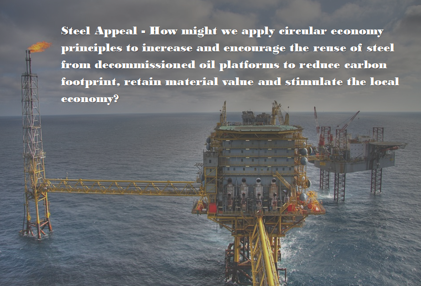
The project brief for this project was named Steel Appeal. It asked how might we apply circular economy principles to increase and encourage the reuse of steel from decommissioned oil platforms to reduce carbon footprint, retain material value and stimulate the local economy?
To begin this project, I brainstormed ideas of how the steel from decommissioned oil rigs could be used to create something sustainable whilst retaining the value of the steel itself by creating a mind map to help try and expand on ideas I had.
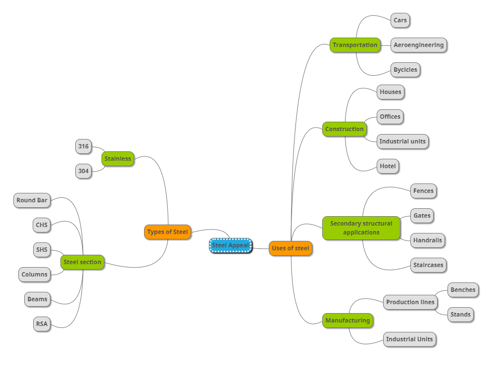
Once I had finished the mind map, I had a clear idea that I felt met the brief well whilst incorporating the skill set I have already and would help further develop these skills by applying them to new areas and feilds. My answer to the brief was to use the steel from decommissioned oil rigs to create small costal villages where both food and water supply is incredibly poor. These villages will be built from the grade 316 stainless steel that is the primary material found on oil rigs as the grade 316 helps to prevent from rust and helps stop corrosion from the salt and harsh elements that are experienced on the oil rigs whilst at sea. The buildings were to be built as portal frames that can be sheeted and insulated to either keep them warm or cool depending on the environment they were built in.
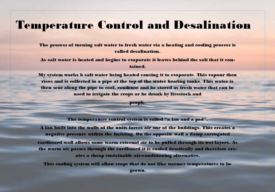
I began researching ways to create a fresh water source from salt water. I learnt about a process desalination. This is where salt water is heated and evaporates. The fresh water rises to the top of a tank and is taken to be cooled and condensed back into clean, drinkable water. When the water evaporates it leaves behind the salt that can be cleaned from the tank and removed.
From this reserch I decided I would create a long pipe that extended out to sea that could pump sea water into tanks on the shore. Again, all materials were to be found on the oil rigs which helps keep the cost incredibly low. These water tanks could then be heated via a sustainable energy source such as solar, wind or hydroelectric power to allow the water to evaporate and rise inside of the tank. Once evaporated the water would leave behind the salt and travel via tubes to a separate larger tank. This is where the water would be cooled and condense into clean drinkable water. This can be used for both drinking water and irrigation for crops and livestock that previously were unable to survive in the harsh conditions with limited shade, high temperatures and a lack of water.
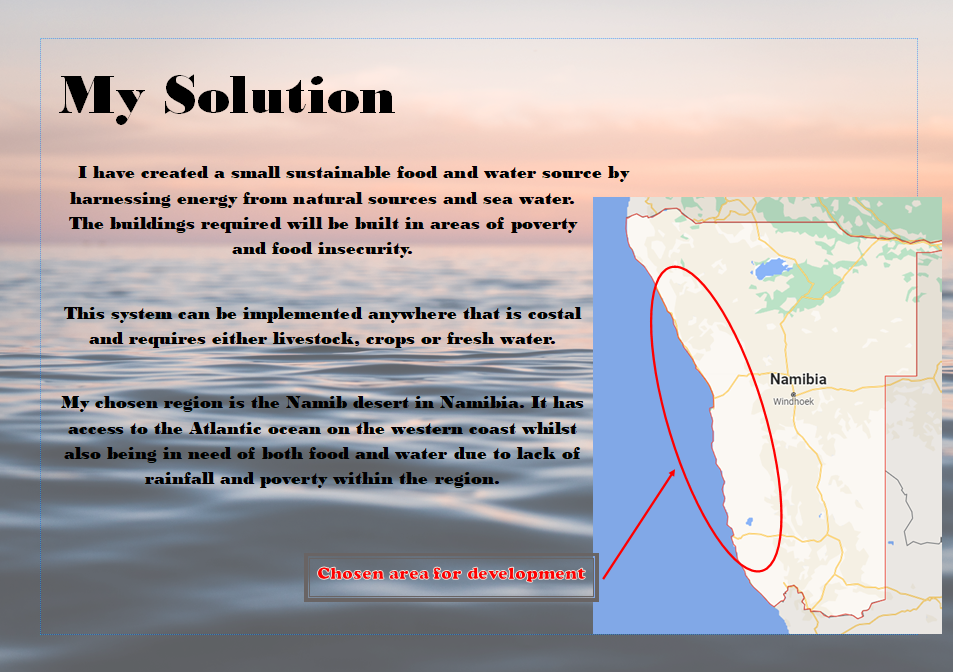
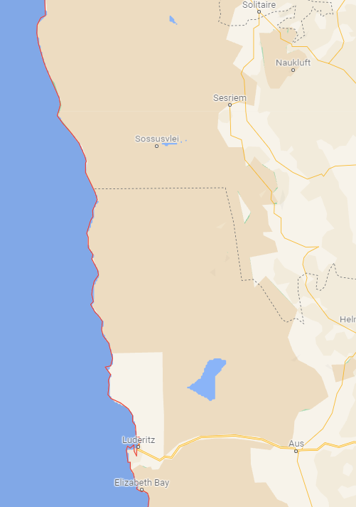
Once I knew how I was going to answer the brief I began looking at areas where I could base my project. After looking at places around the world with food and water issues that were also costal, I found that the Namib desert in Namibia was the perfect place to begin. Namibia is located on the south west of Africa and has a large coast line that runs along its western edge. Due to having a incredibly high level of poverty in the region and a lack of rain there is a requirement for both a food source from crops and livestock whilst also requiring fresh drinking water.
To begin my designing stage, I created a theme board on Pinterest for portal frame designs and construction ideas. From there I began to look at environmentally friendly ways of heating water and providing power to the region. This then allowed me to begin creating designs and setting out my area of the namib desert for construction.

To start my designs, I sketched out a plan view of how I felt would be best to set out the site. This included creating areas for both solar panels, accommodation, livestock sheds, agricultural sheds and water tanks.
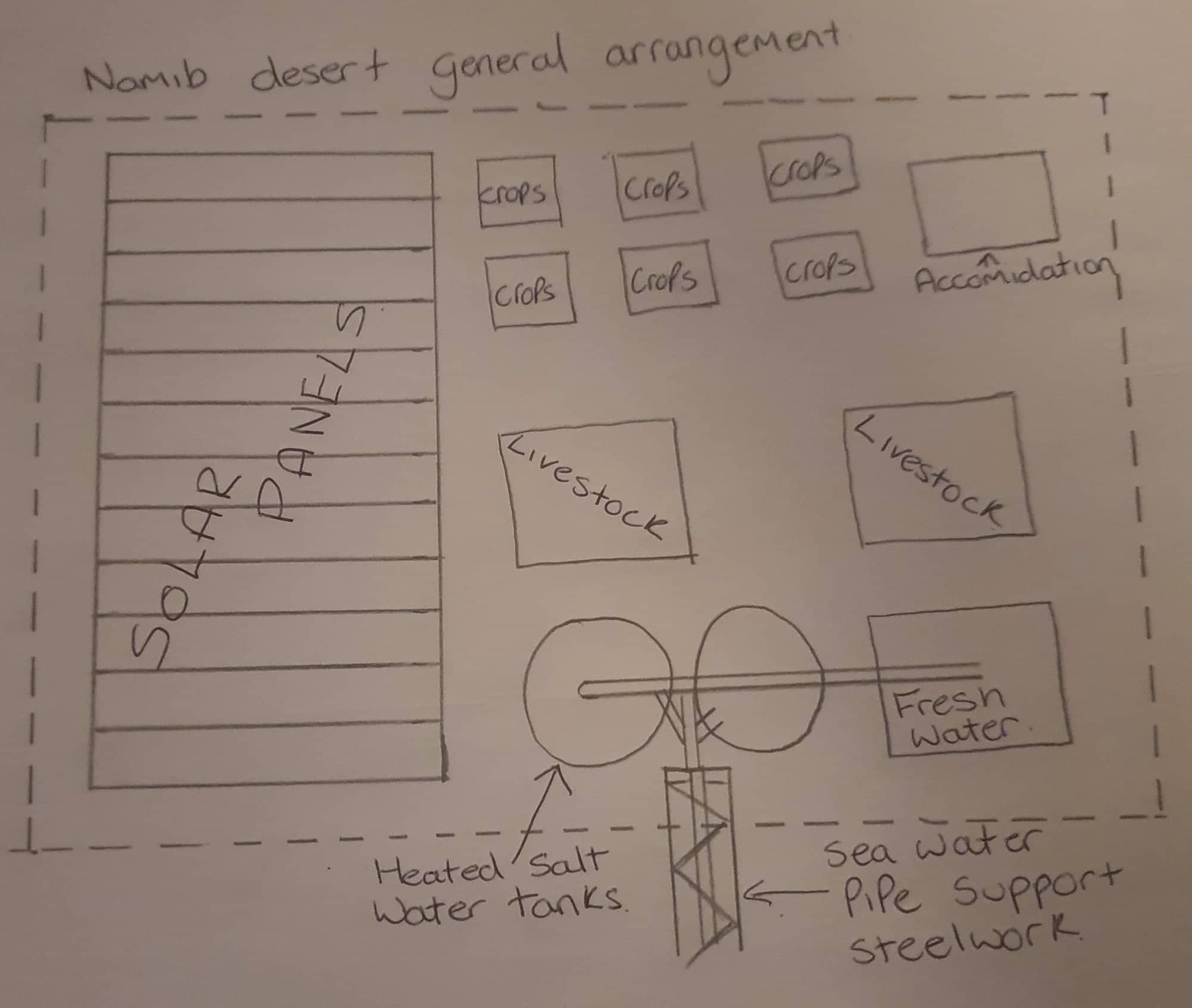
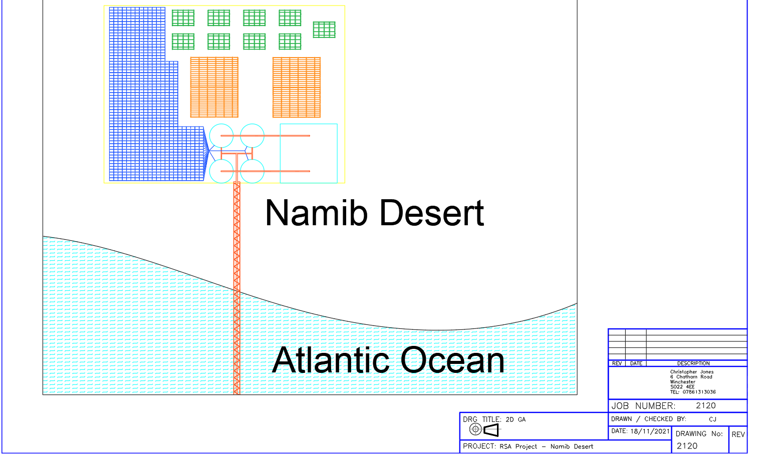
Once the area had been planned out, I felt I could further this design and add a scale to it by creating it in Auto CAD. This would allow me to accurately set out the buildings positions ready to be created and rendered in Revit. To start with my Auto CAD drawings I plotted a 75x75 metre square to give myself a boundary size. From here I was able to divide this area into my selected 5 sections.
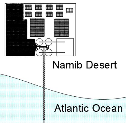
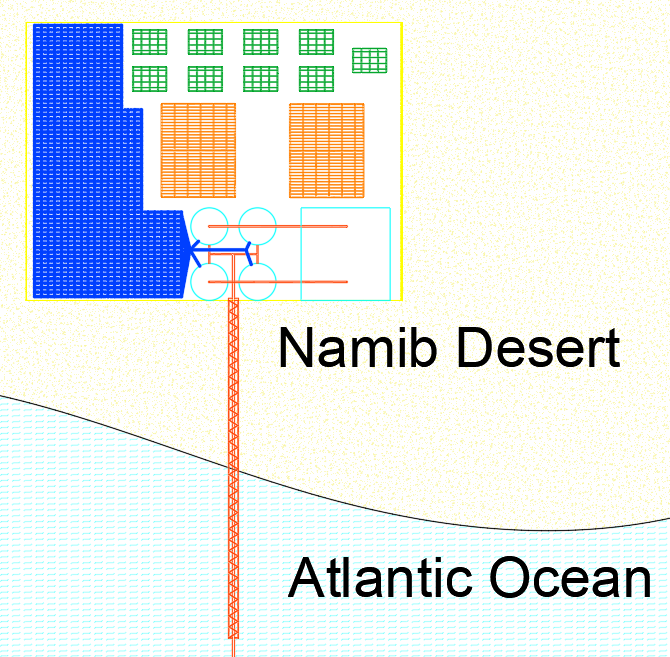
These areas were then colour coded in the layers tab to ensure the buildings could be clearly identified. I would be able to then use this 2D general arrangement to import into Revit to help with my plotting of the structures within thee 3D architectural program.
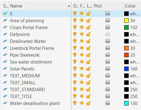
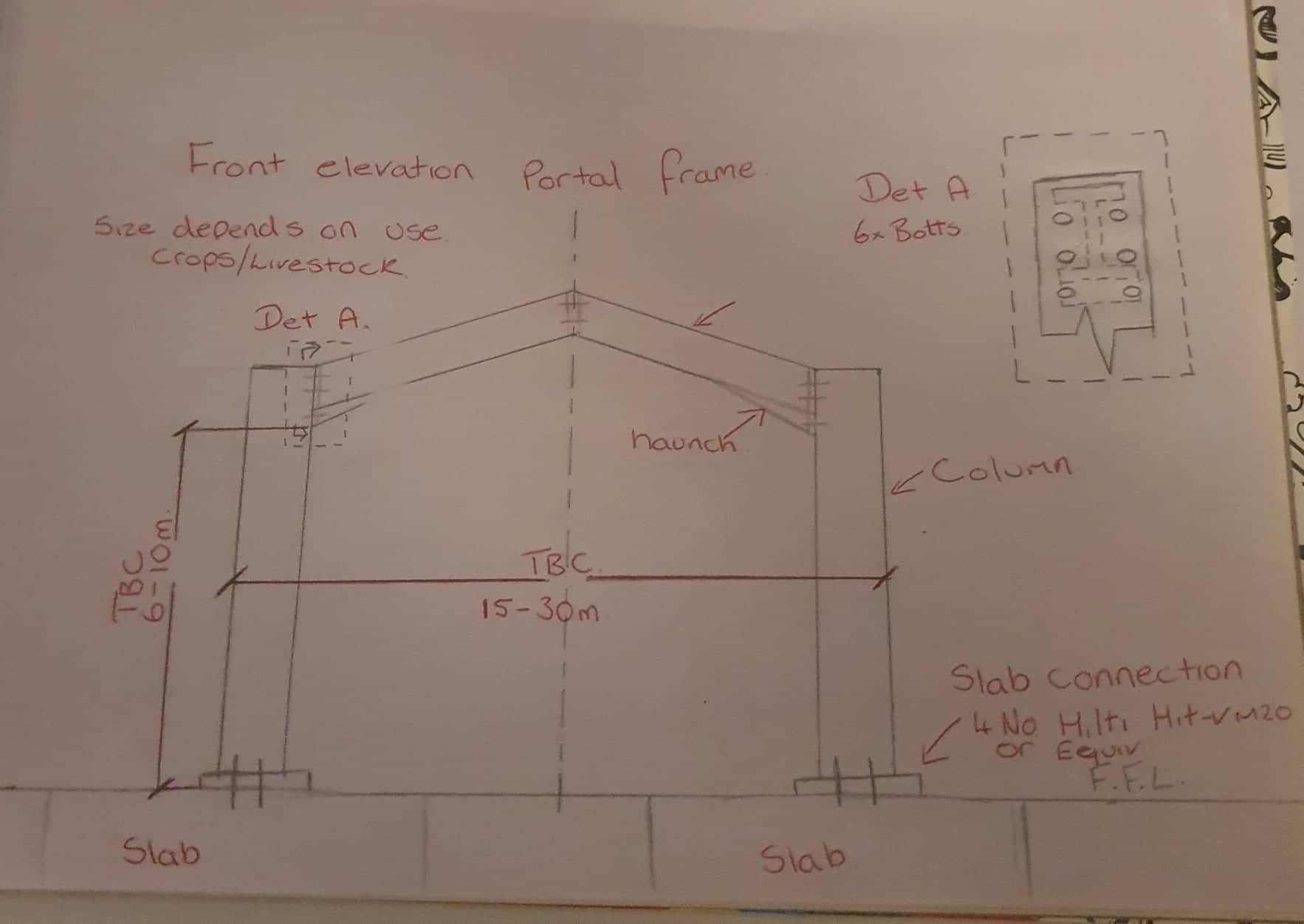
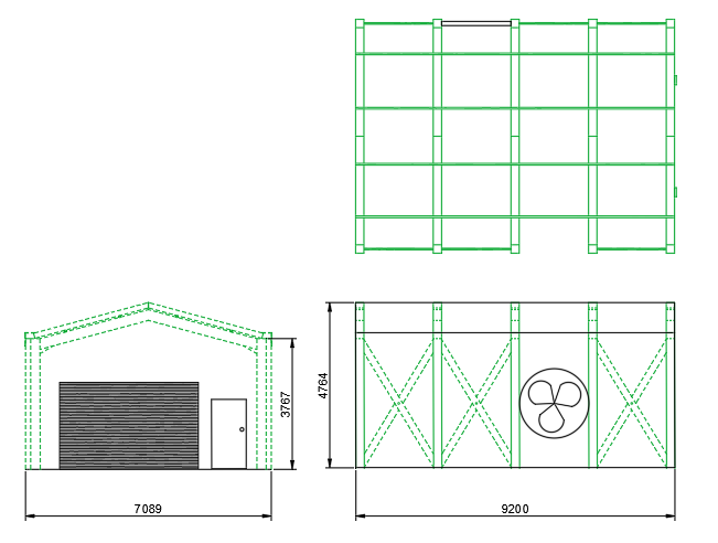
To further help with my 3D creations I drew 2D elevations giving myself dimensions for the accommodation portal frames and the agriculture sheds. These dimensions can then be transferred to my 3D Revit drawing to ensure that I have constant continuity through my designs.
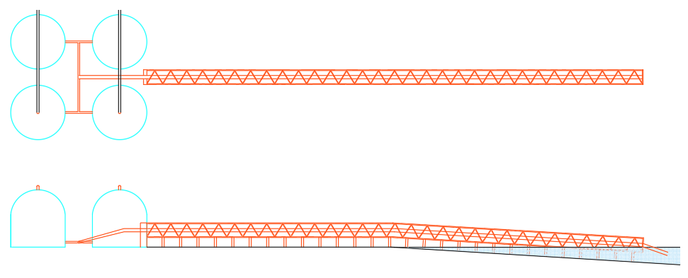
I also created an elevation drawing from the 2D plan view of the pipe support steelwork that runs to the sea for the intake of sea water. This elevation shows the columns and bracing around the pipe that would help protect it from rocks that may be moved by the ocean or stronger waves that could potentially damage the pipe. The elevation view gives me a top of steel work height that can be carried forwards to the Revit model that will again maintain design continuity.
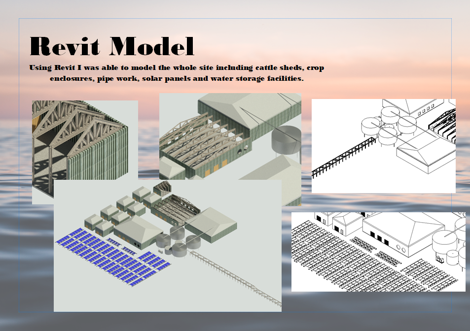
To begin the Revit model, I started by creating a new metric architectural drawing. I then chose to link my 2D general arrangement plan DWG. This gave me the setting out points of my columns, solar panels, water tanks and pipe support steelwork that was input whilst using Auto CAD.
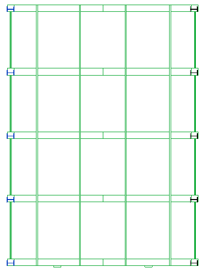
Once this had been inserted, I was able to begin creating the column layout for the first smaller portal frame unit. I began by importing the correct column size library that I required for construction. One the columns had been imported successfully I was able to click the column command, choose the required size and then enter the pre-determined Auto CAD height of 3767mm from base to top of column. This could then be copied to each of the other positions it was required around the building.
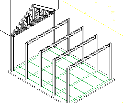
Once the columns had been inserted into the model, I could begin to make up the portal. I selected the chosen height and angle for the rafters and inserted them in and then used the slice command to remove the excess steel at the apex of the rafter. Again, the rafters could then be copied along the columns to create a set of portals that can then have a roof applied to them.
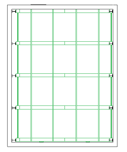
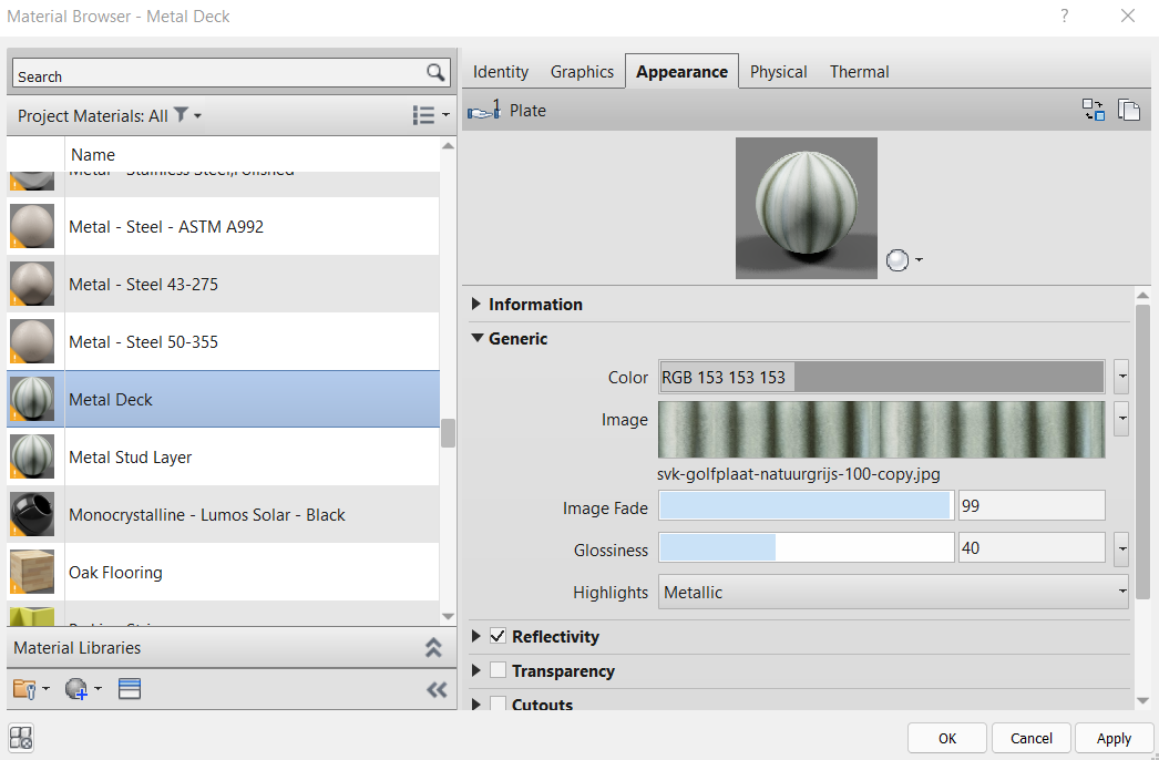
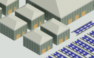
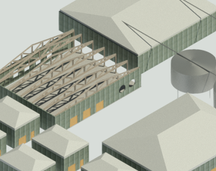
Before I could add the roof to the building I had to create the walls. The walls were to be the same height as the top of column dimension. These 200mm thick walls were placed to surround the columns on all sides of the buildings. From this point I could then add the roof. I had selected the roof command and then selected the outside edge of each wall. This places a roof over the internal components of the portal whilst following the wall outline. The roof material was then changed to be a reflective material to help reflect sunlight and remove heat from the internal of the buildings. The walls were given a corrugated sheet finish which is a cheap material that provides good protection from the elements outside.
The corrugated sheet material image was scaled to suit the building it was being applied to. The initial image was incredibly small and did not show the required level of detail that was needed to show the finish. This was amended by changing the height of the sample size to 1500mm and the width to 1000mm.
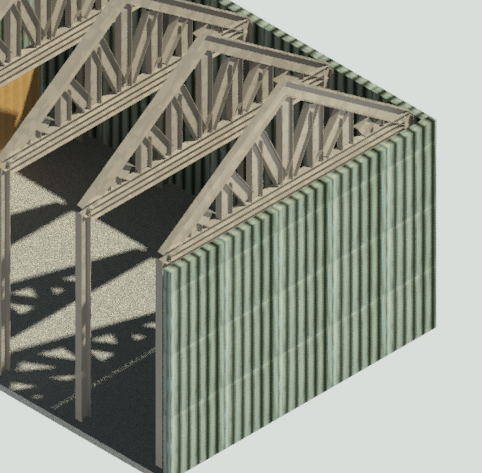
The next area for modelling was the larger units. These were completed in the same was the other portal frames. I have left a roof off one of each style of portal frame to allow for the internal steelwork to be visible.
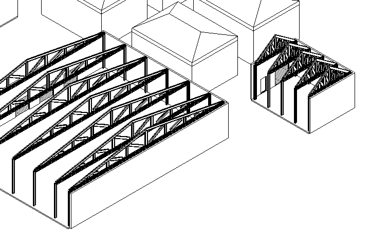
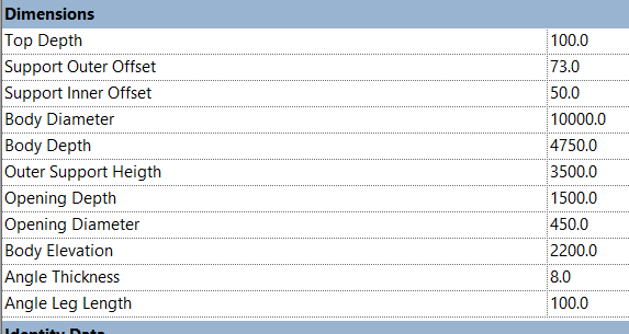
For the next step I imported a library for a water silo. This was then input into the model using the component command. The silo was too small so the sizes were adjusted to ensure the 4 No. tanks were large enough to hold the required amount of sea water.

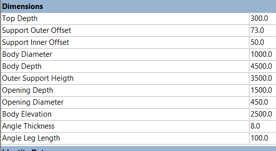
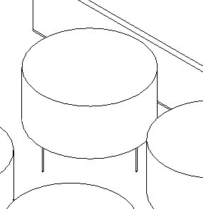
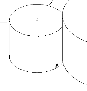
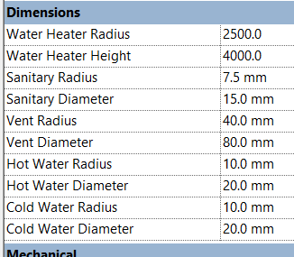
I then imported the library for a water heater. The size of this was also edited to ensure it would be able to heat the required amount of water to allow for the condensation to occur. This was placed next to the four water silos.
The next area for modelling was the pipe support steelwork. I had the plan view already in the linked DWG so I was able to place the columns directly into position. The cross-member beams were also added to provide stability in the structure. I then used the elevation to insert the bracing beams to provide stability from multiple directions due to the constant water forces that would be applied by the ocean.
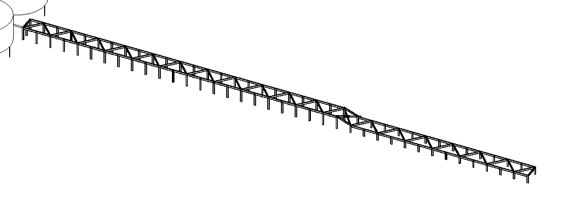

Once the pipe support steel work was created I was able to add the pipe that would take salt water from the sea to the salt water heating tanks. This pipe had to be suspended from the top beams to ensure I was protected within the structure. The pipe I had chosen for this was a 219mm dia CHS.


The pipe that is used to transport water feeds into a water pump. This pump then sends the water into the 4 water silos. This water is then heated within each silo via thew water heated. These silos and fed at the bottom via the water pump pipe and there is a pipe on the top that will collect the condensation and is sent to a large water storage facility. As the water travels along the pipe that enters the fresh water storage facility the condensation will cool and turn to salt free water.
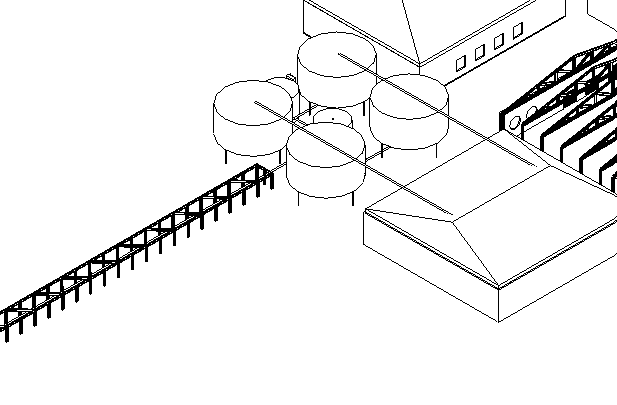
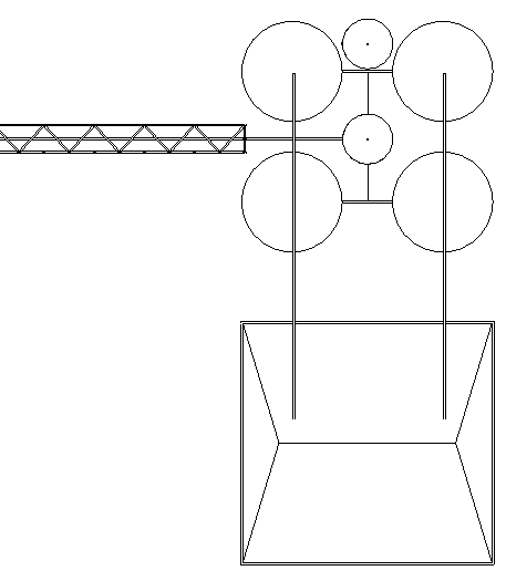
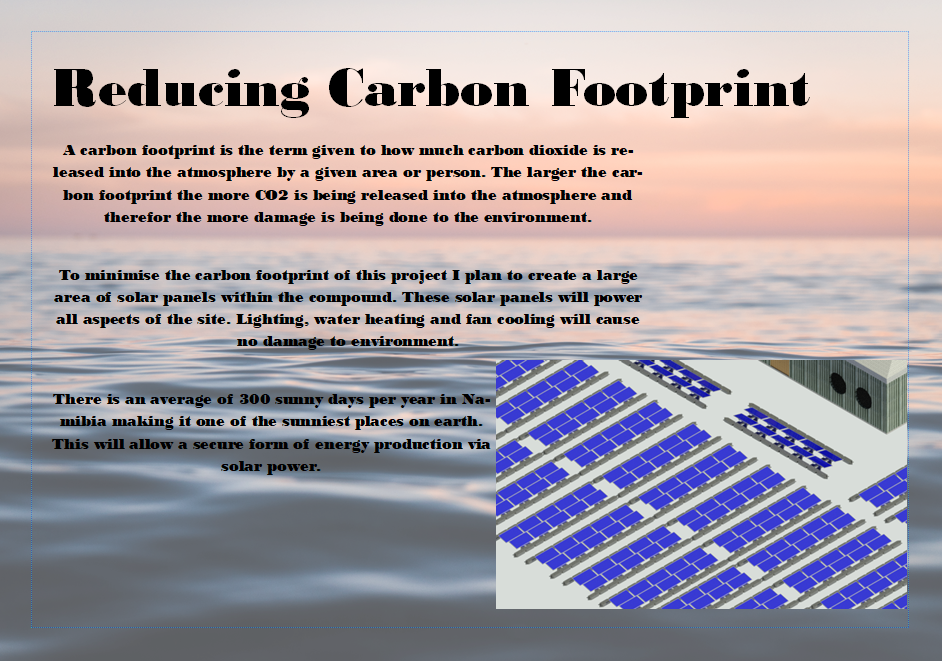
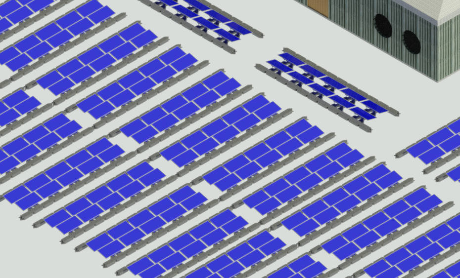
I then had to add the solar panels that will power the water heater, pump, lights and building cooling systems. These were inserted from a library. I had to scale the family model prior to importing them into my model as they were too small. The panel size was doubled. I was able to follow the layout from my 2D Auto CAD plan to ensure I would receive enough power from the sun to gain the required output. I final placed a power storage unit next to the water heater to allow the energy to be stored and transferred to the required area of the site.
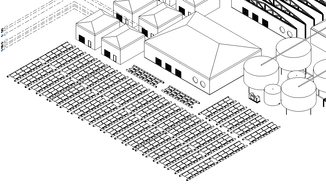
The final addition to the model were the roller shutter doors and cooling systems. The roller shutter doors were input into the model via a library. They were then placed on the front of each building along side a standard external metal door for ease of entry and exit. After researching eco-efficent cooling systems I found a cooling system that I have included into the project. It is called a fan and pad system; the fan blows air from inside the units to the outside creating a negative pressure inside the unit. On the opposite wall a slightly damp corrugated cardboard panel is placed in sections. The internal negative pressure draws the warm external air into the unit and it is cooled as it passes through the cardboard panels. To complete this I have created fan holes and cardboard panel sections within the walls of the units to allow for the installation of this system. The temperature can be controlled by changing the fan speed thus changing the negative pressure inside the unit and the amount of air that is therefore required to pass through the cardboard panel.
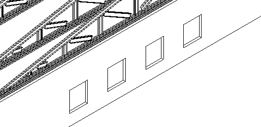

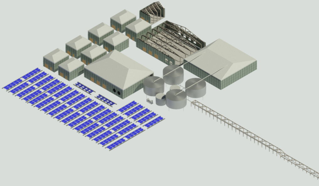
To complete this project I created numerous drawings and renders to show the sizes of each building type and the finishes that have been applied via editing the materials used in construction.
RSA Boards
Once the Revit drawings had been completed, I was able to create my 6 RSA board to help with the presentation of my project. These boards were designed to show and explain the various areas I wanted to talk about with my project. They can be used to for further insights into the technology and systems that would be required to use to create this project.
