Semester 1 Computer Aided Design
During my first semester of university I have looked at creating various models both 2D and 3D in Autocad whilst also looking at what is required for creating industry level drawings.
Paper Fold House
The first task to complete on my Computer Aided Design Course was a paper fold house drawing. To start on the task, I began researching ideas for paper fold design houses and to see how other people were designing and manufacturing them. I conducted this research on the image categorising app Pinterest. This app allowed me to gain some background knowledge on my topic before starting my own project.

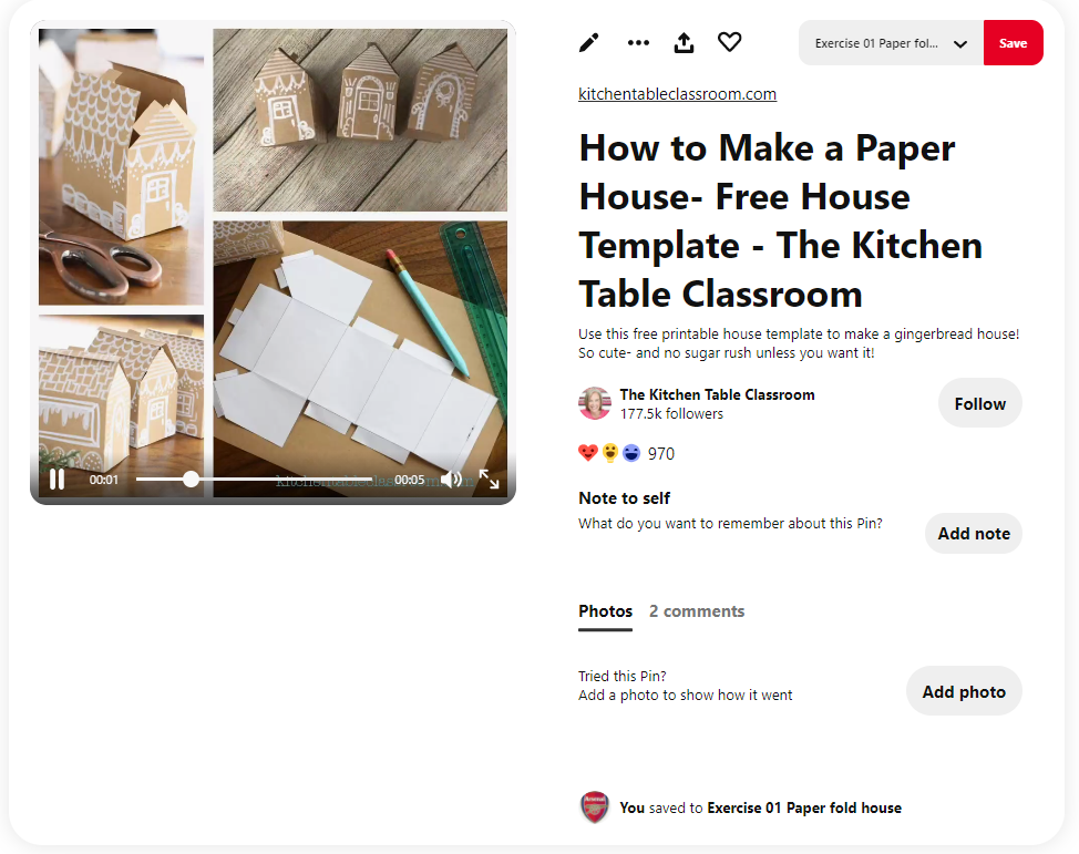
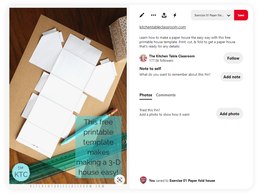
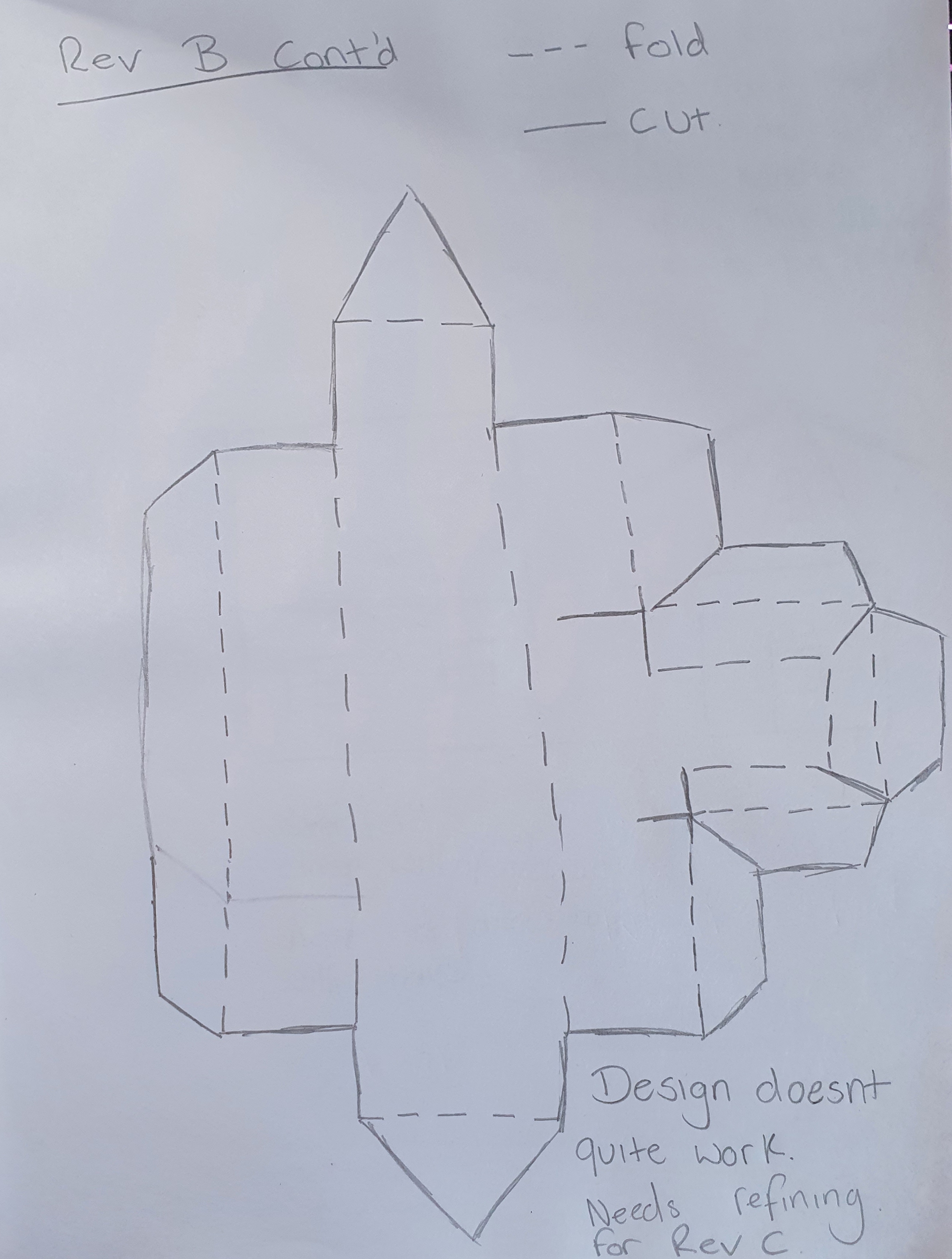
From this research I gained good knowledge of what was needed to create a paper fold house. This included how they were constructed using tabs and folds, design styles I liked and how to turn the design into something useful for everyday life. From this position I began to sketch out ideas I liked. I started with a basic idea of a paper fold house and revised the sketch to ensure it incorporated everything I required in the design.

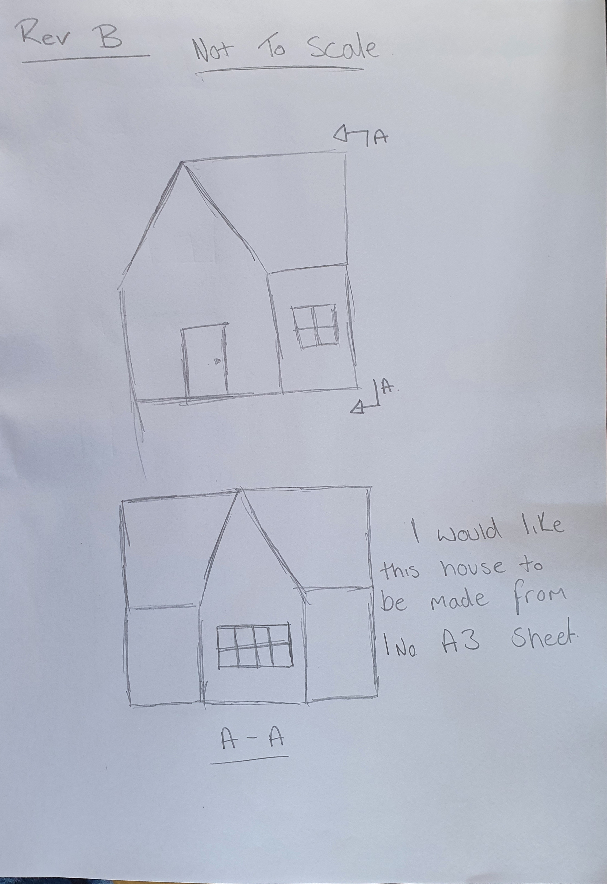
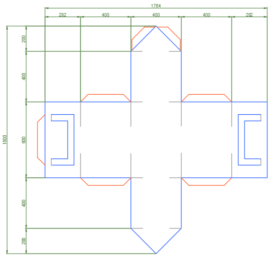
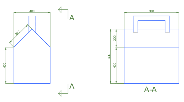
For my final revision sketch (Rev C) I decided to add handles on the roof to my house design. These handles would add a practical element to my design. The house could now be used as a bag to carry or hold items.
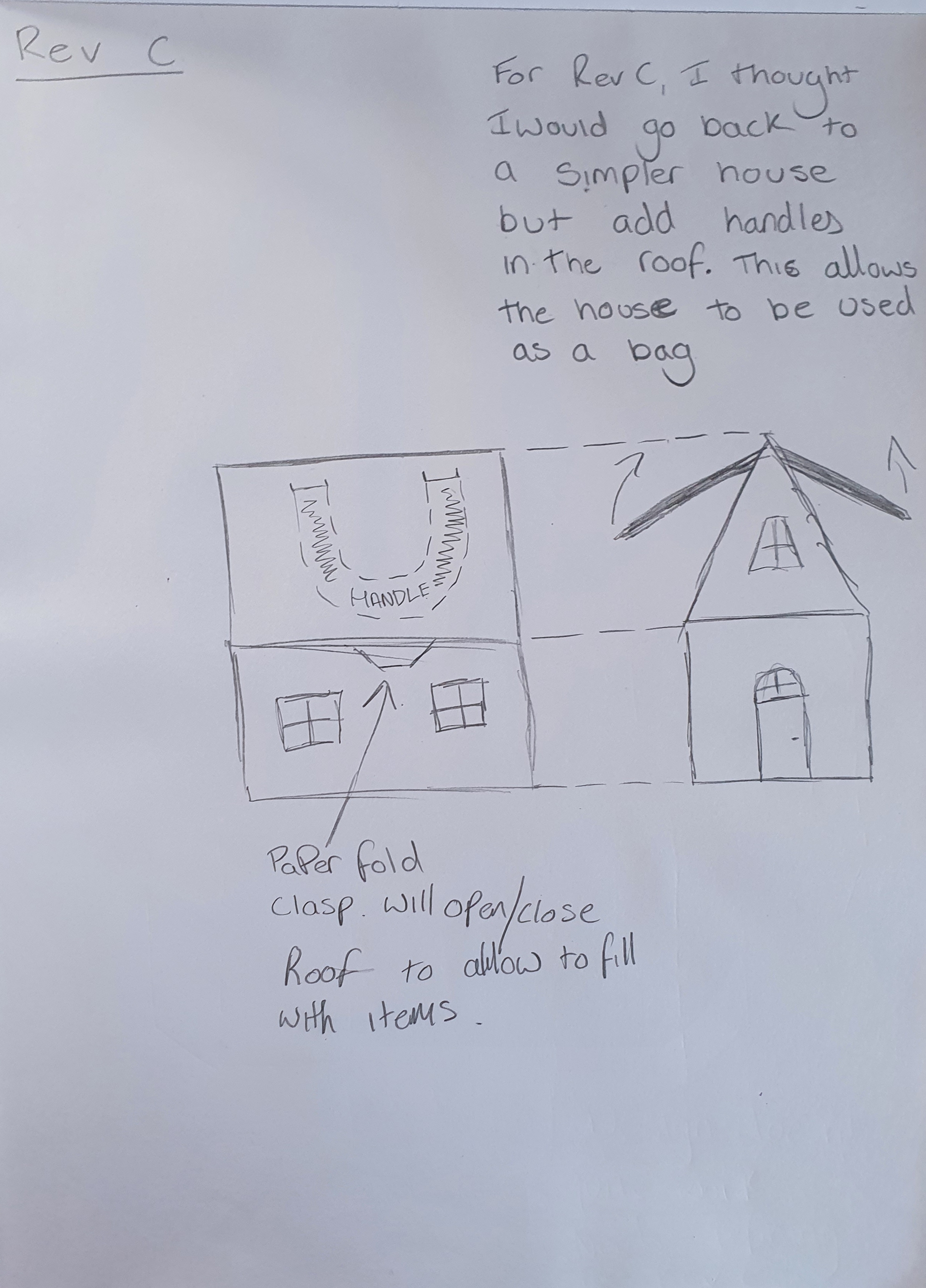
Once I was happy with this design I then transferred my sketch into 2D Auto CAD. This was completed as both a net drawing and a finalised contructed detail drawing to show how the house would look once built with elevation drawigns. the hosue can be seen drawn to scale and complete with layers table to show folds, cuts and tabs on the net drawing
Artistic scene with CAD
Before creating a business card I began researching what current designs were currently availabe or had been made by others and shared online. To find these images I used websites such as Pintrest to create a board of design ideas. Using Pinterest allowed me to view a variety of ideas and takes on what was a very diverse design brief. My research concluded there are two main types of business card that are often used. The first is a simplistic style of business card that quite often lacks colour or any eye-catching features and works in a subtle way. The second type is the opposite. It is a card that stands out and often has a main noticeable feature that would interest the recipient. This can be seen in the forms of 3d designs, colourful images or simply the material that the card is constructed from.
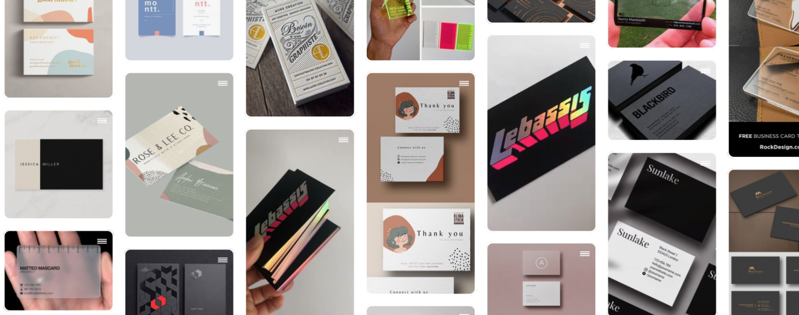
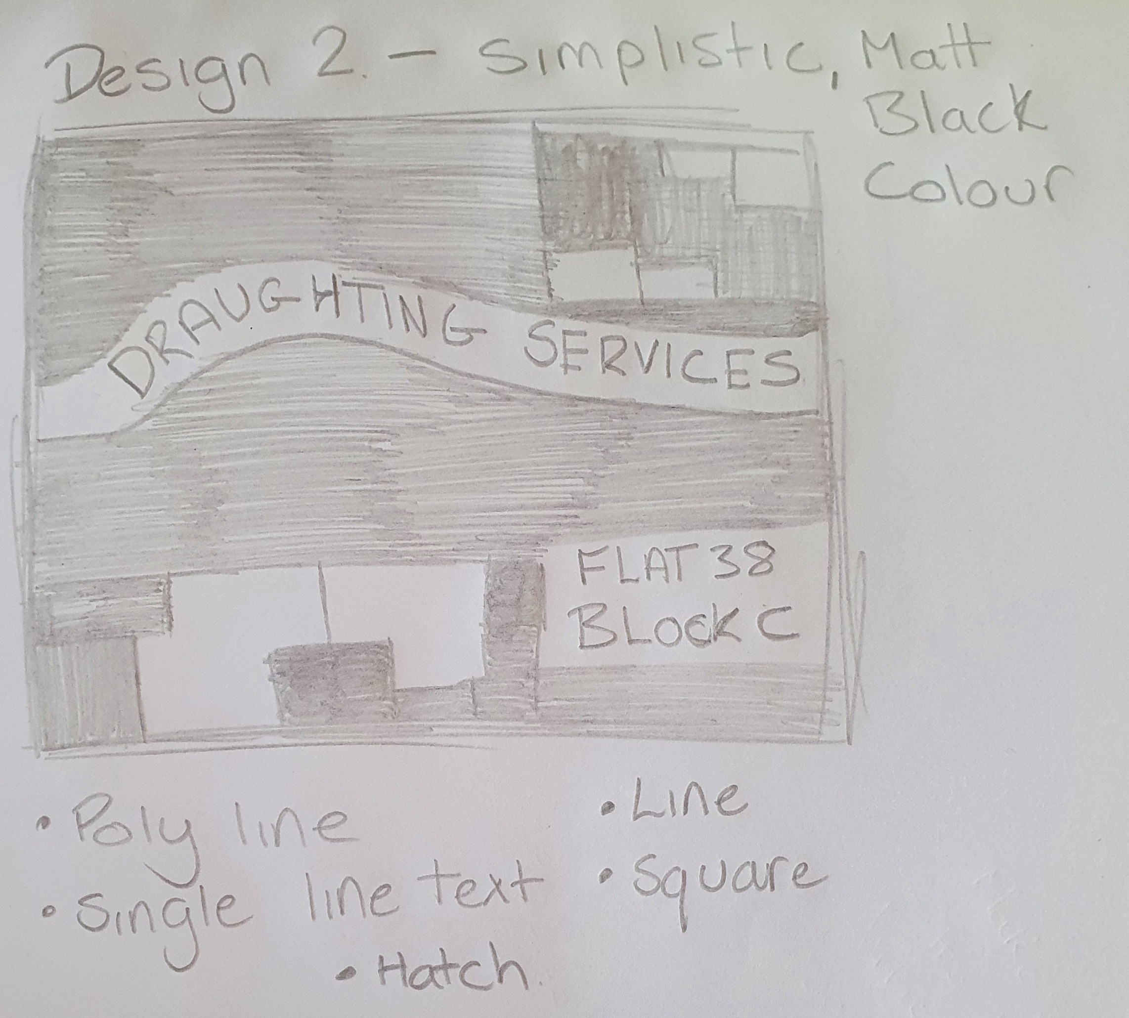
Once I had completed my research, I began to design my own ideas. I initially decided I wanted to design a minimalist business card. However, after completing three designs, two simplistic and one that was designed to be eye catching I preferred the latter more.
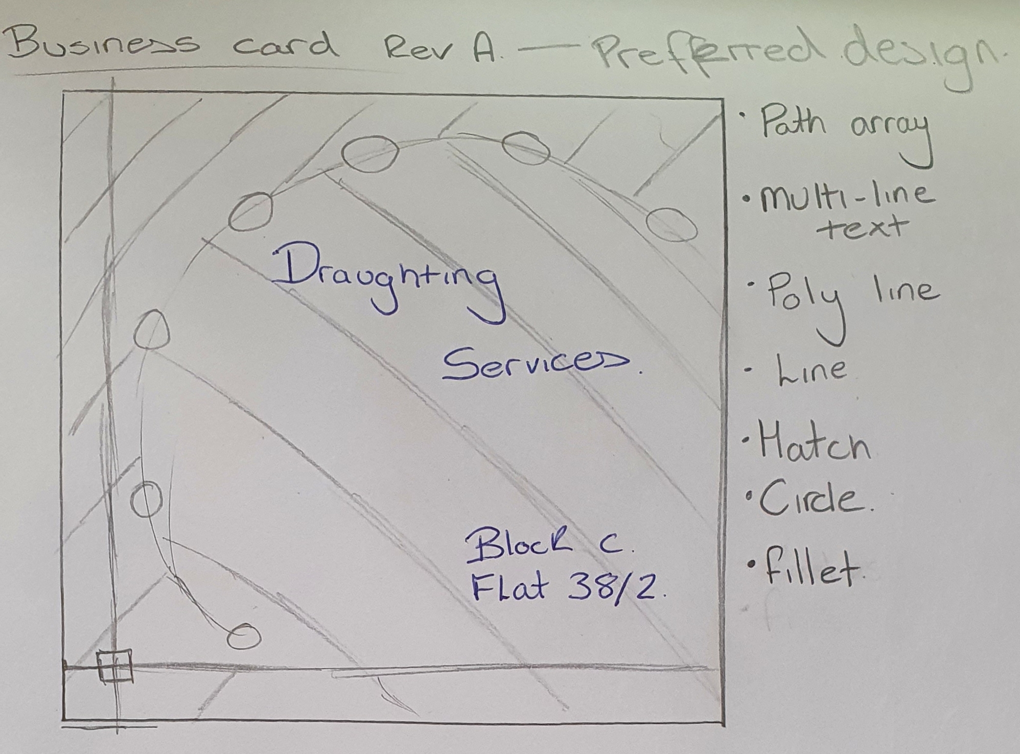
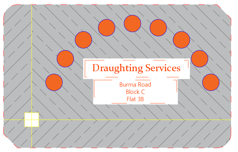
After my designs were completed, I moved on to create the first design in 2D Auto CAD. I prefered this design over the other as it was more complex and I felt it would appear better when placed onto a business card. The information was also clear to view. This business card involved using multiple tools withing Auto CAD. These included • Line • Polyline • Square • Circle • Path array • Fillet • Hatch • Text
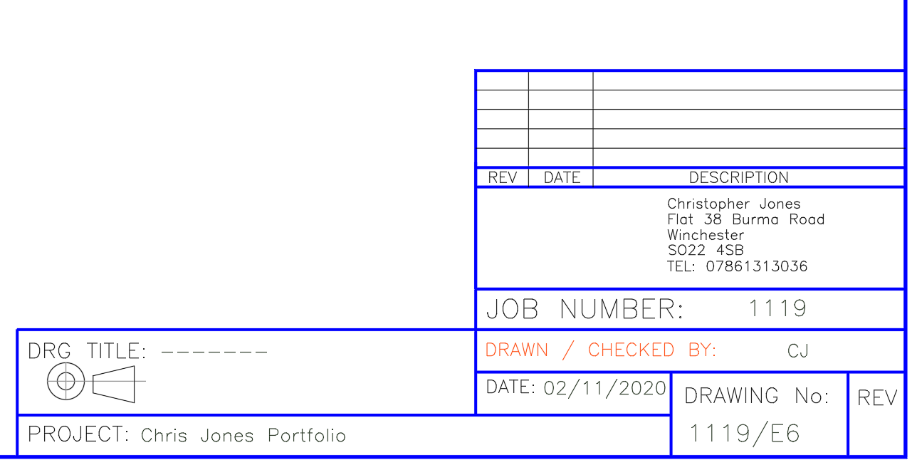
Drawing Borders
A drawing border on a drawing is where all the relevant information to the drawing can be found. This information will relate to both what can be seen in the drawing, what it relates to in the project and how the drawing has developed over time. It is a hugely important aspect of the drawing and should be included on every drawing that is used on a project. Included in the drawing border are the following • Drawing date • Initials of the draughtsman • Relevant Job Number • Drawing number • Address of the company who own the drawing• A drawing title• Project name • Revision number• Revision changes.
The drawing borders I have created are scaled to three sizes for different drawings. These are A4, A3 and A2. These are the most common drawing border sizes for industry. These three paper sizes then have been transferred into two rotations, landscape and portrait to allow whatever is being drawn to fit into the paper space.
Drawing Formats
Whilst using Auto CAD drawing files (.DWGS) can be exported and saved to many other file types to be used in other computer programmes. This is to allow the drawing to used by a range of people who may be using different software or require the drawing that has been created to view certain aspects of drawings created on different computer programmes.
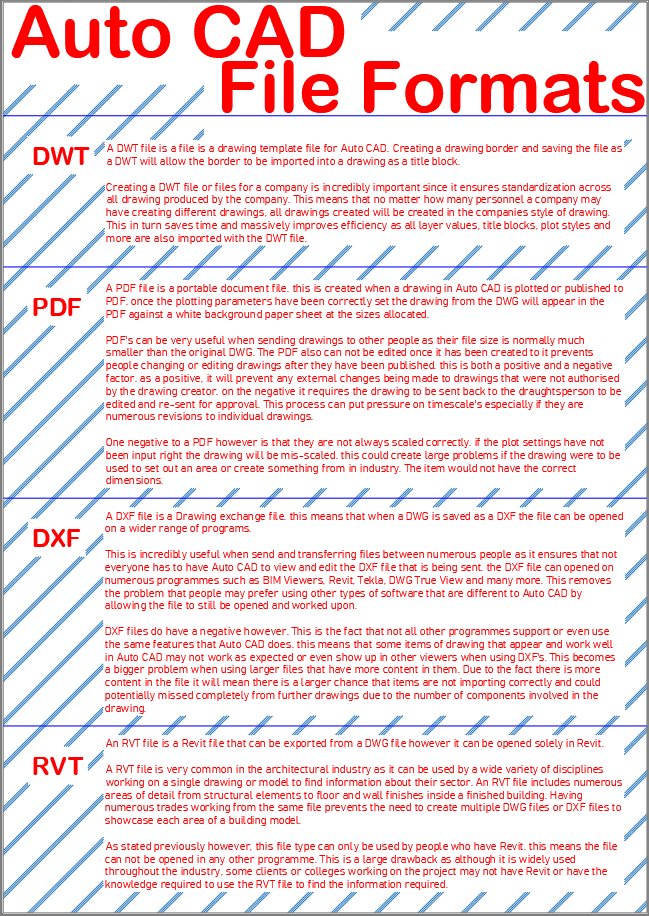
A DWG file is a standard drawing file in Auto CAD that allows the user to create and edit drawings using the programme. A DWG is the most common form of file type used by Auto CAD. In a DWG File the user can create both 2D and 3D drawings.
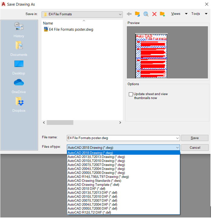
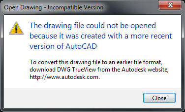
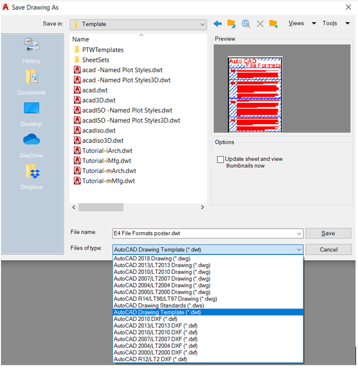
To save as a DWG file type the user must click on the drop-down bar at the bottom of the save window and select the DWG file type. This is where the user will notice multiple DWG file Options each from a different year of release. In Auto CAD, each year the programme is further developed and updated adding new features and aesthetics to the software. This means that if the Auto Desk programme is not kept up to date then the user will not be able to open any DWG files that are saved in a later version than they are current using i.e. A user on CAD 2007 could not open a DWG that had been saved in a CAD DWG 2012 format. However, this is not true when a person using newer software would like to open an older document. Newer versions Auto CAD will be able to read older documents without facing problems.
To save a file as a DWT format the user must open the desired project and create the template. This requires the user to input everything from creating a standard drawing border that can be used for every future job, a layer system that acts as a base for standardised dimensions and text that can be further developed to add mor layers when required throughout future projects.
Once this has been complete the file is ready to be exported as a DWT. This can be done by selecting the bottom drop down menu on the save as window and selecting DWT Drawing template.
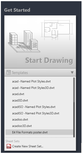
From here the drawing template file can be opened every time a new project is created by clicking the drop down below the new drawing button on the Auto CAD home screen and selecting the .DWT file you require.
A DWF file is web drawing file that is used for sending drawings via the internet.
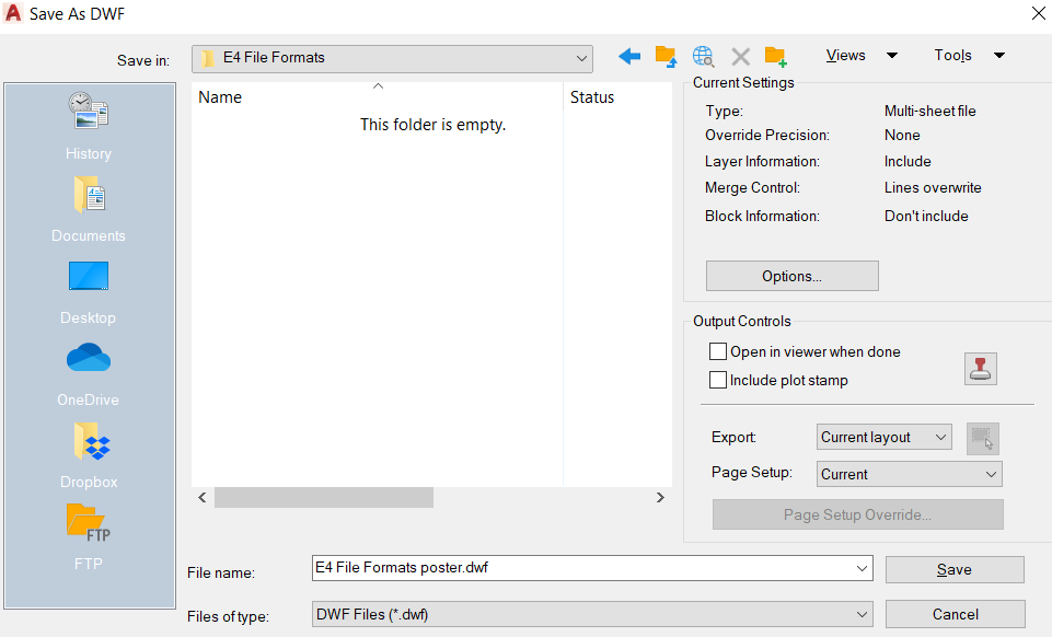
This is very useful for people who require drawings whether they are clients or colleges that do not have access to Auto CAD or any alternatives due to being out of office or on site. This file type can be opened in an internet browser and allows the recipient to view drawings whilst on a mobile or tablet.This allows for greater accessibility to drawings anywhere or anytime.
The downside to using this file format is that the file takes a snapshot of what is included in the DWG document. This means the file cannot be modified at all it can only be zoomed or rotated by the user. This can be a problem for gaining different elevations of a 3D model that may not be shown in separate details on the drawing.
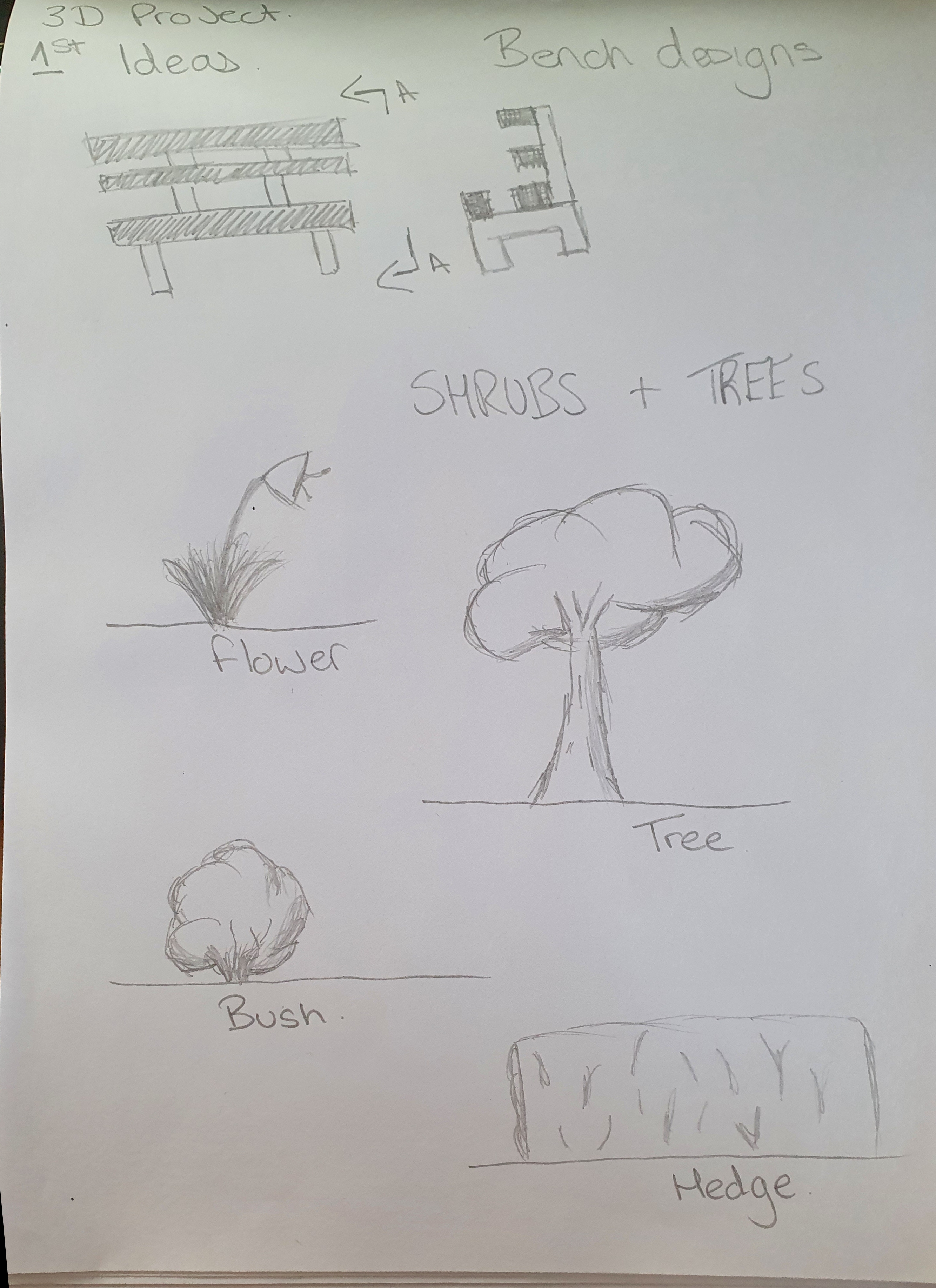
Sketching, scamps and observations
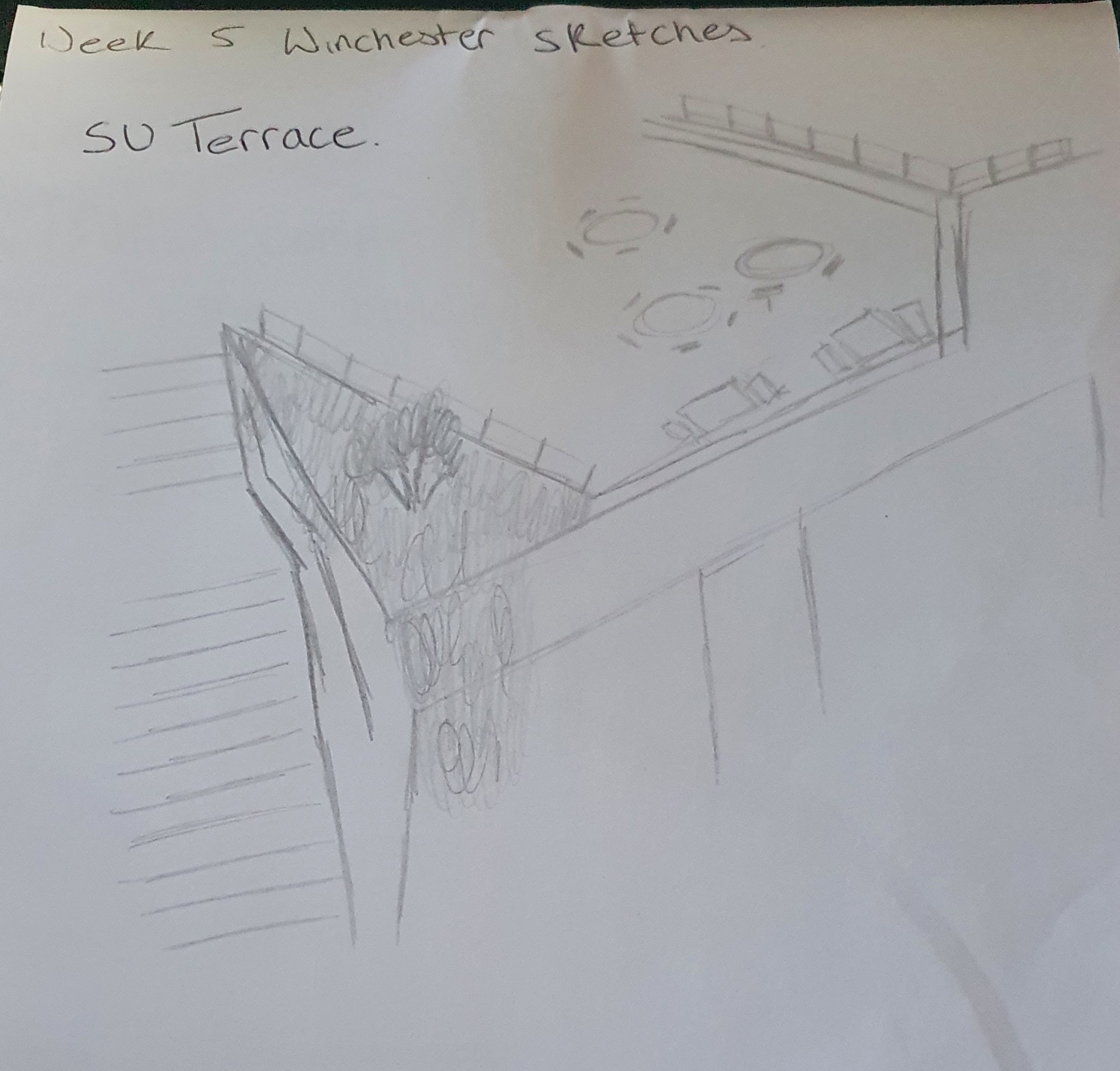
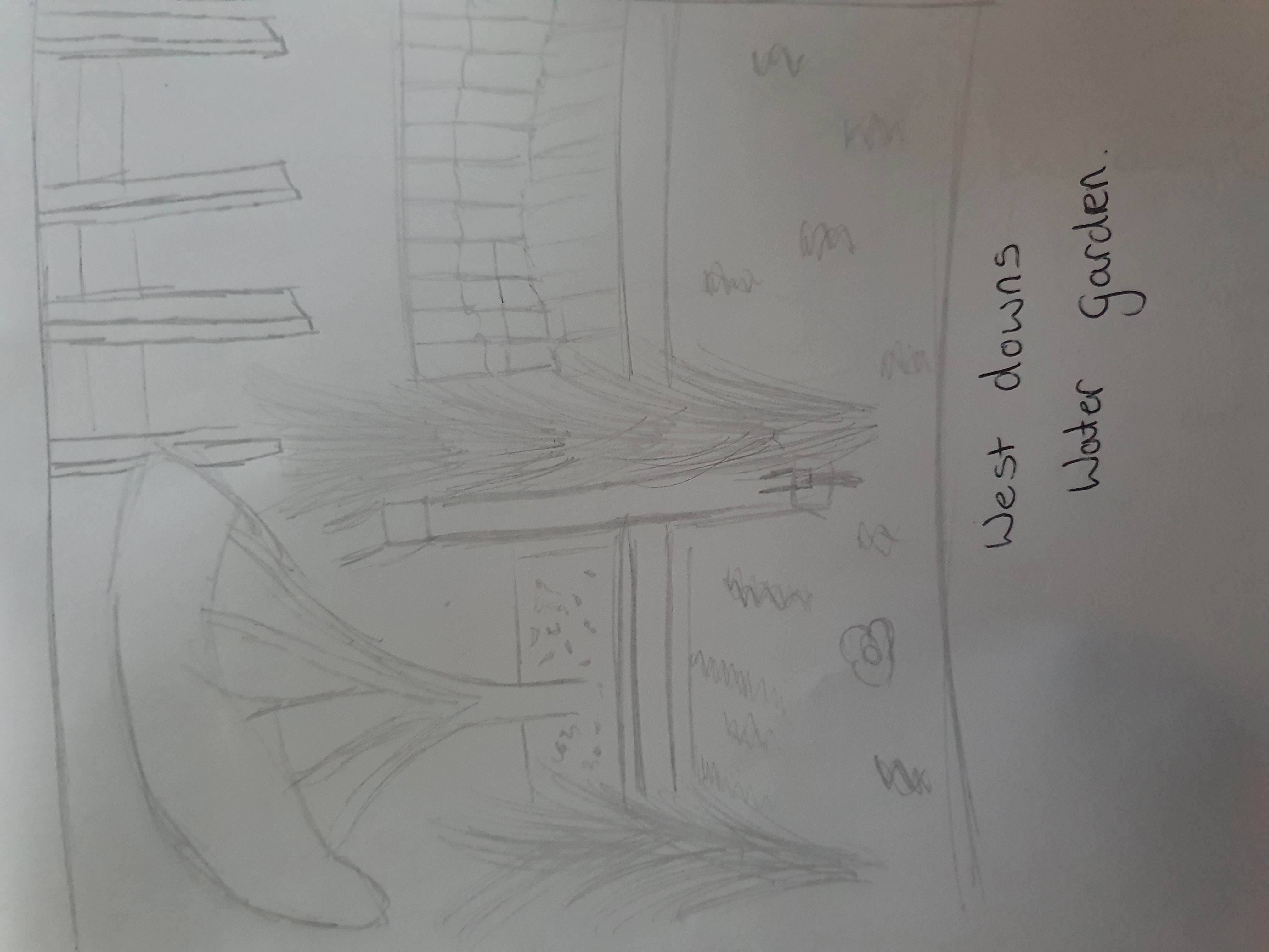
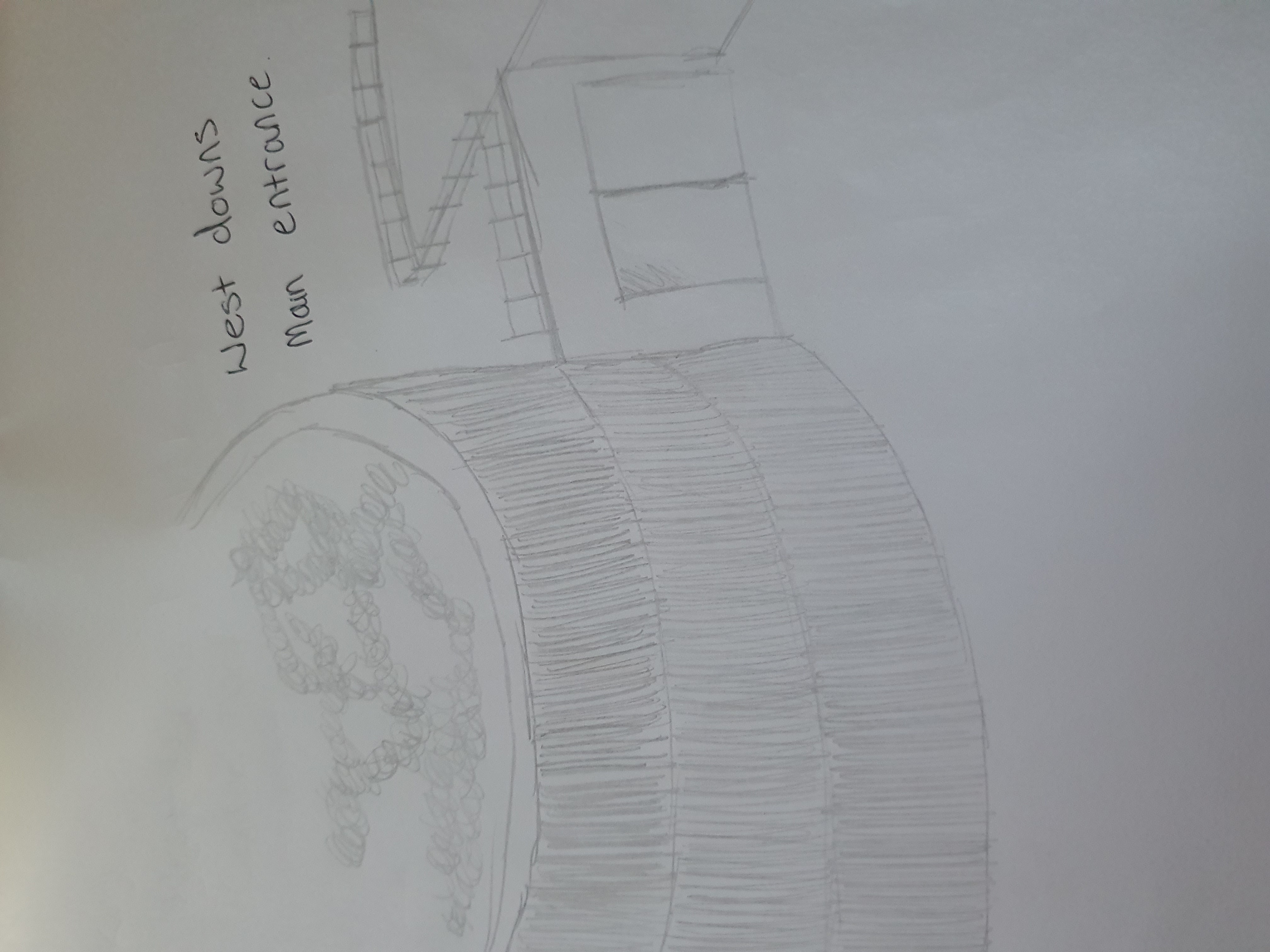
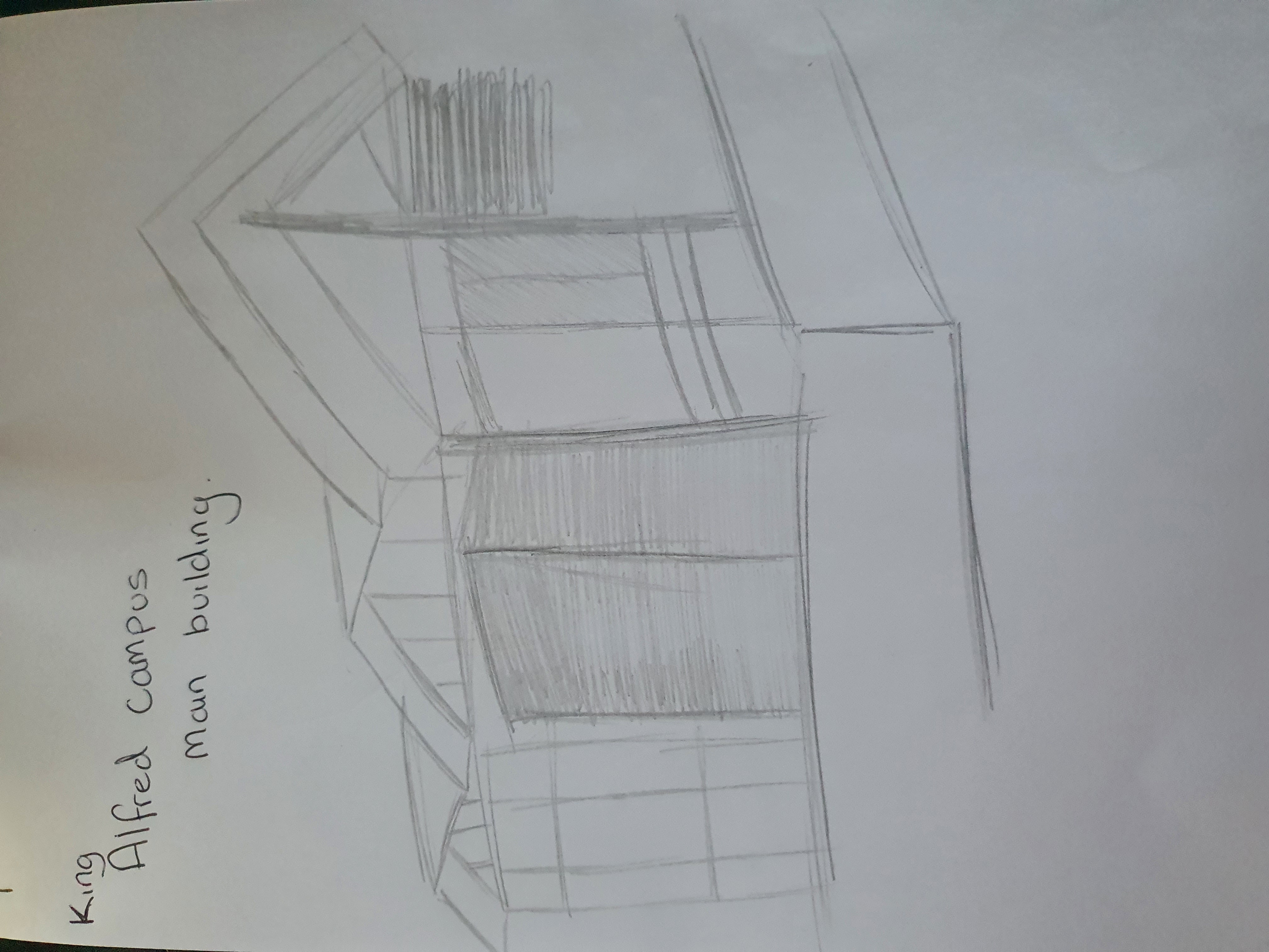
For this exercise I sketched areas of Winchester University that I felt had good architectural elements and designs. There were many areas I couldve chosen to draw however I managed to find five areas to detail that I felt had the best areas of architecture.
The first area I chose to sketch was the students union terrace at the king Alfred quarter. Here you can see the shop front below the terrace and the tables laid out above next to the windows in front of the bar. You can also se the stairs that connect the two levels.
The second area I decided to sketch was the library pond garden at the West Downs centre. This area is designed to be a modern, peaceful garden in the centre of the campus. Included in this garden are trees and grass bushes surrounding a small waterfall that flows into a pond. Surrounding this area are the library and the west downs centre main building that uses a an oxidised steel exterior design.
The next area I chose to draw was the main entrance of the West Downs centre. This building is very new to the campus and with this it has a new architectural appearance. The vertical rusted box section style design that is featured around the front of the auditorium is an eye catching design that I feel works incredibly well with the rest of the building
The fourth area I chose to sketch is the roof of the main building on the King Alfred campus. This roof is a large architectural area that has been designed to look like sharp waves flowing over the roof of the building. The south side of the roof canter levers off the end of the students union building over the terrace below. This is supported by a large cylindrical column that gives structure to the roof. These two factors are why I chose to sketch this roof.
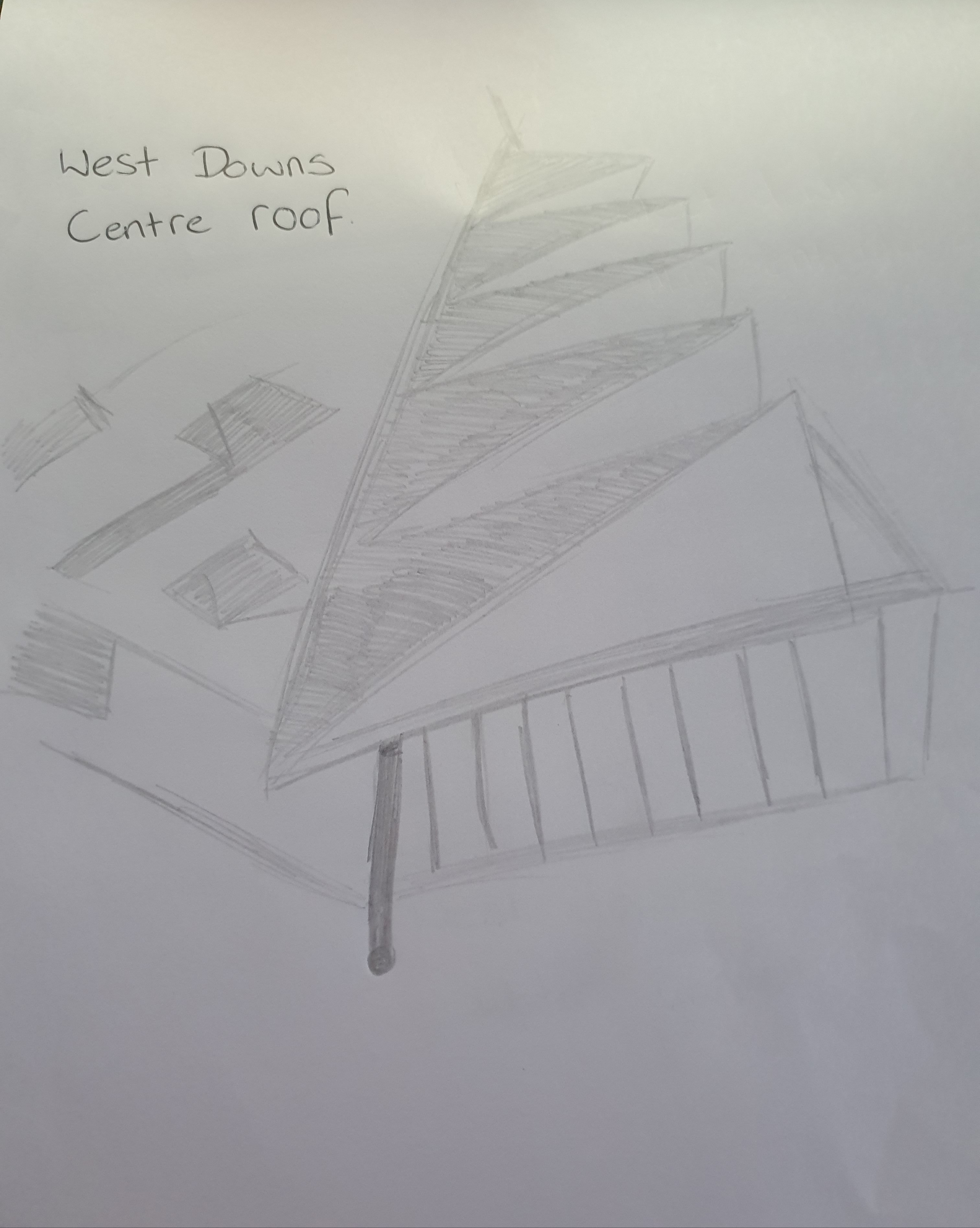
My final area to sketch was the West Downs centre roof. This area has taken a different angle to the pointed design that is on sketch four. This roof top is waved and sloped towards the left-hand edge of the building giving it a wedge design. However, the roof also canter levers off the south off the building and is supported by a cylindrical column.
3D Modeling
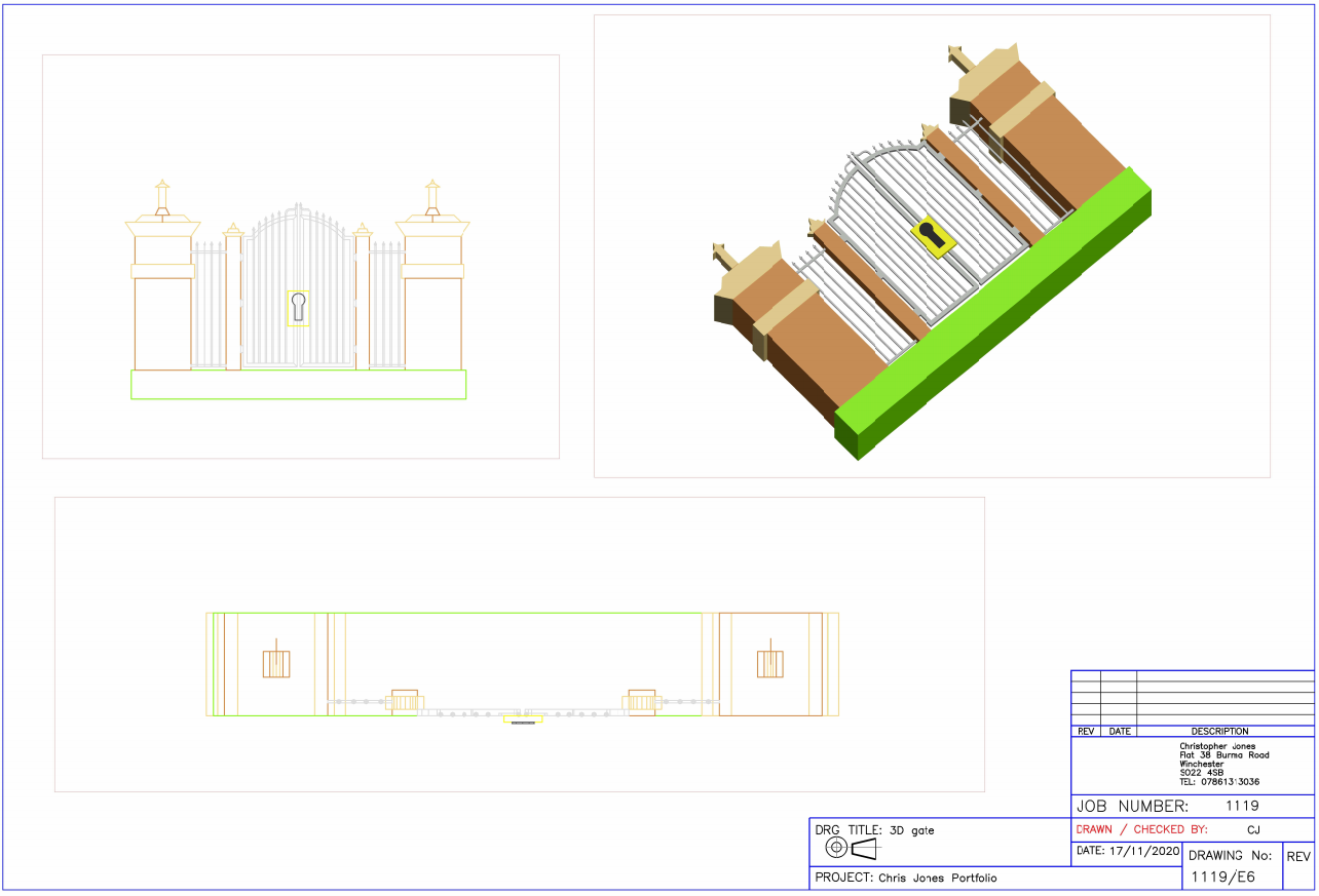
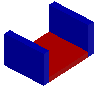
My first 3D model I have created is of an architectural gate. The main gate was constructed using cylindrical extrusions to create the infill bars whilst the exterior frame was created using poly lines that have been joined together to create one shape allowing the extrusion. The drawing presented below shows a 3D View of the gate with both a side elevation and front elevation.
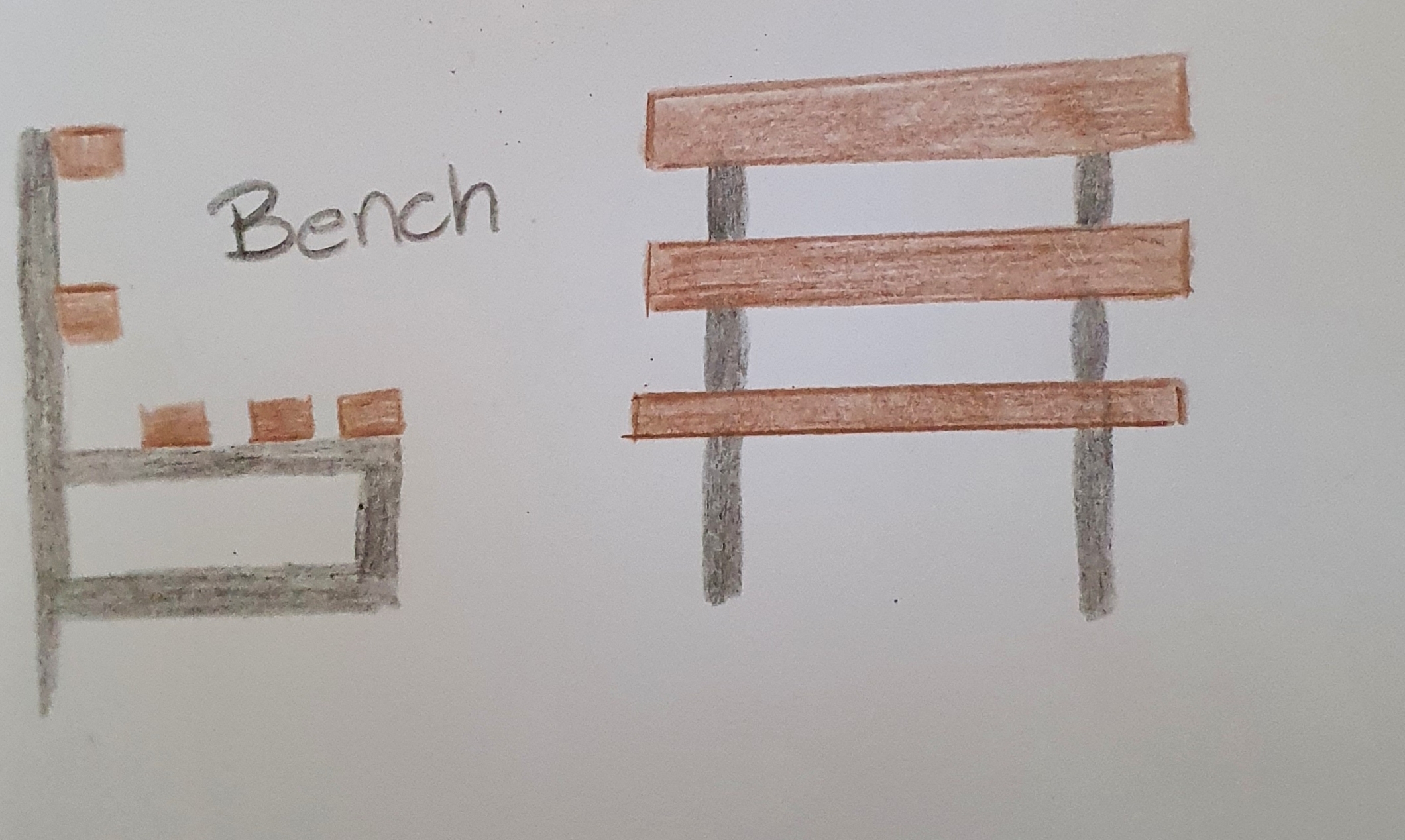
My second 3D Model was for a bench. This 3D model was created by extruding multiple shapes that were initially drawn in 2D using different elevations by moving the UCS to fit the drawing plane required. The drawing presented below shows a 3D View of the bench with both a side elevation and front elevation.

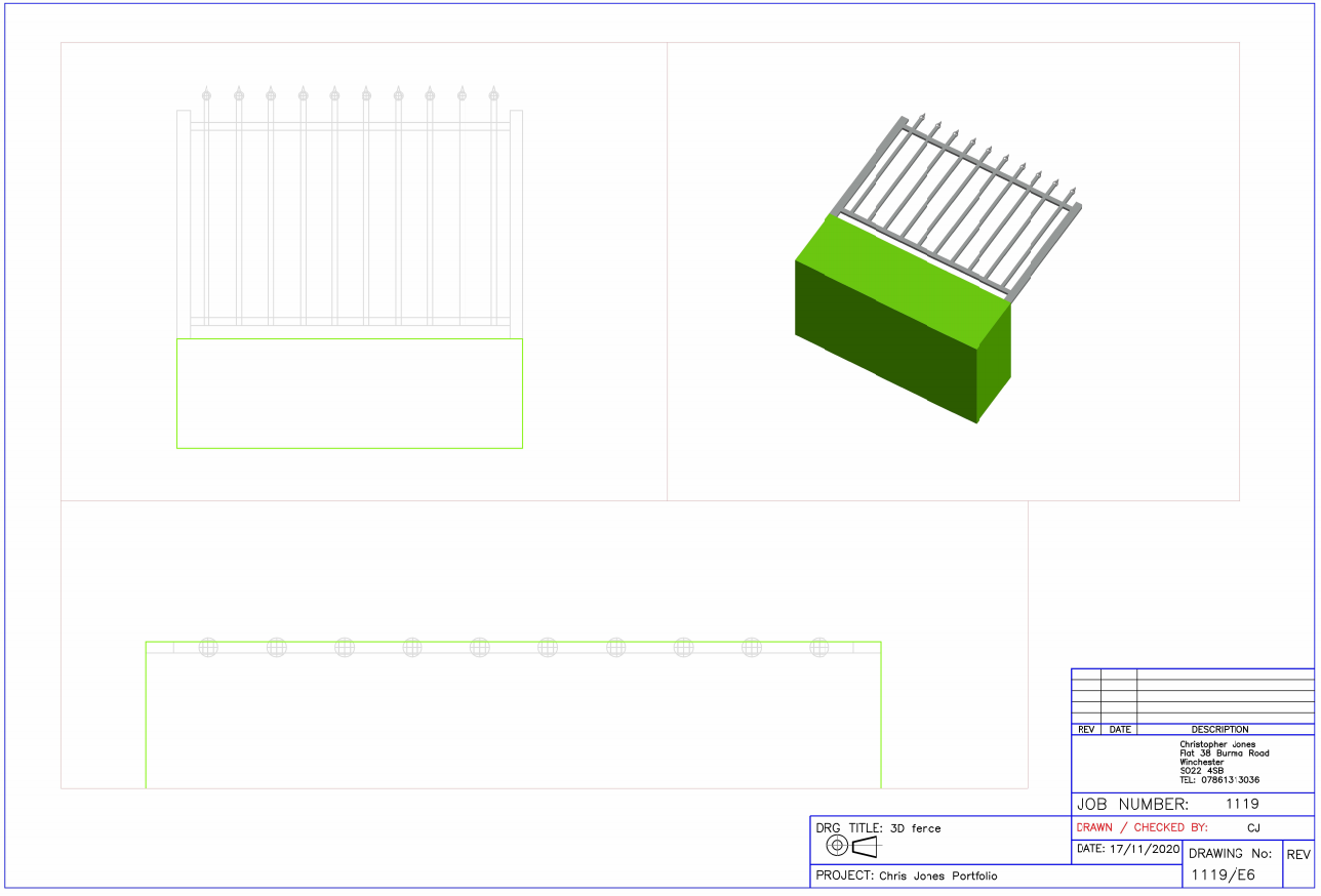
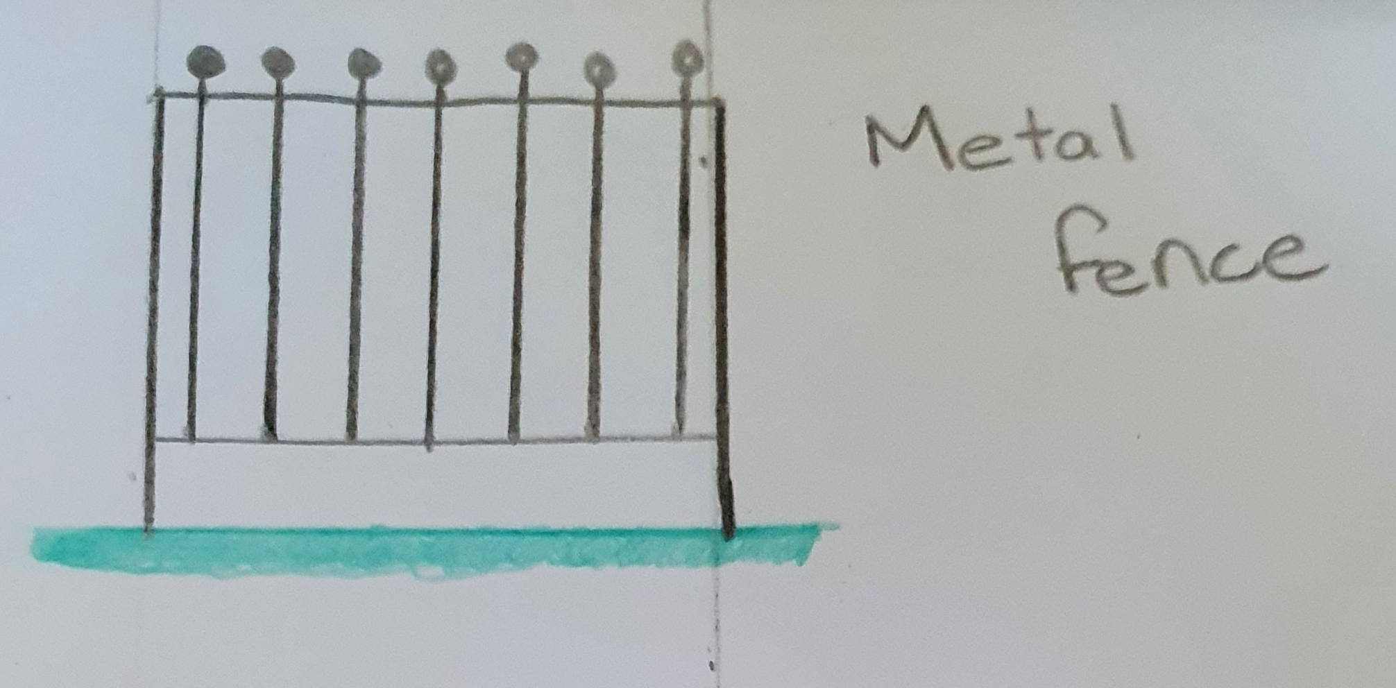
My third 3D model is of a metal fence panel. The drawing is a 3D solid model created first in 2D and extruded to create each individual component
Story baord for project work
When designing the level, I began by putting together a mood board on Pinterest that focused on level designs for other games. This helped me to see common themes that run between games that are similar to the one we are looking to produce.
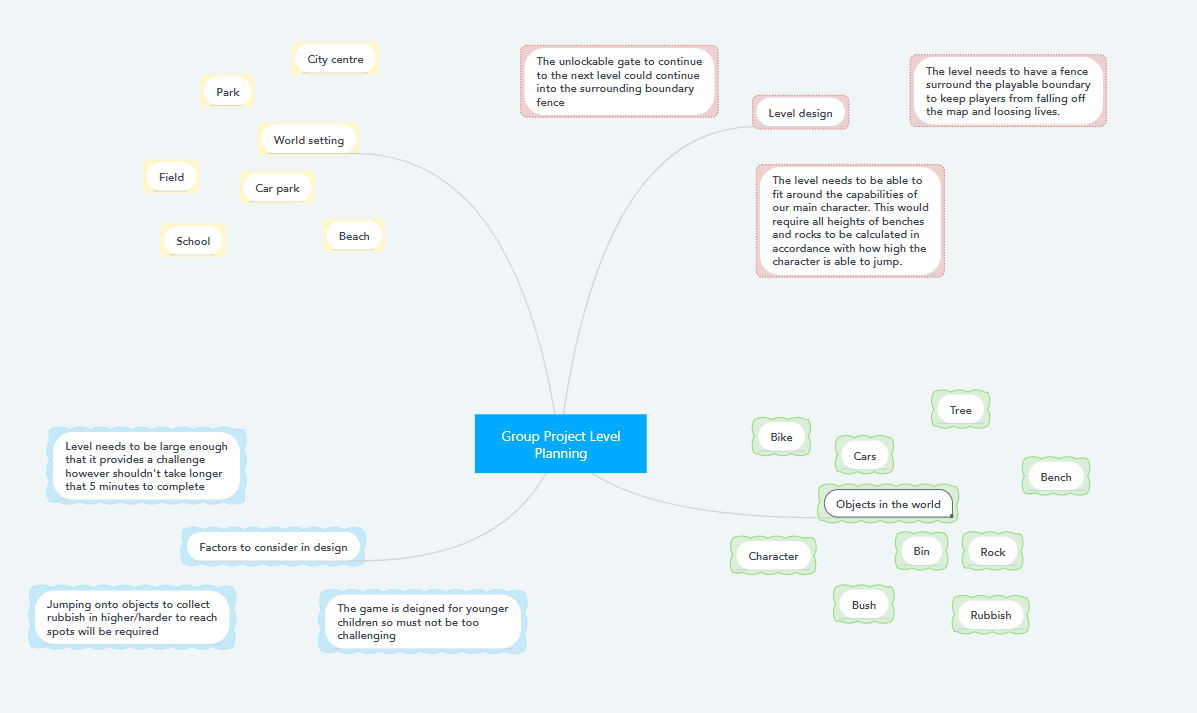
Once I had researched other games and images to get an understanding of level design I began to apply what I had found to how I was going to design and create the level. I did this by creating a mind map showing a variety of elements that I thought might work when designing the level and areas I felt I might need to focus on in the future when It came to sketching and creating in Auto CAD.
I could then begin to focus on sketching out possible level designs and ideas for areas within the level. I was able to create 2 basic level sketches that would work well within the confines of how our game was designed to play.
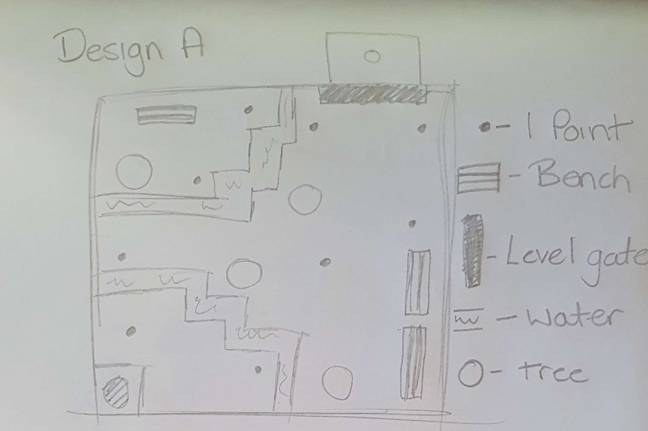
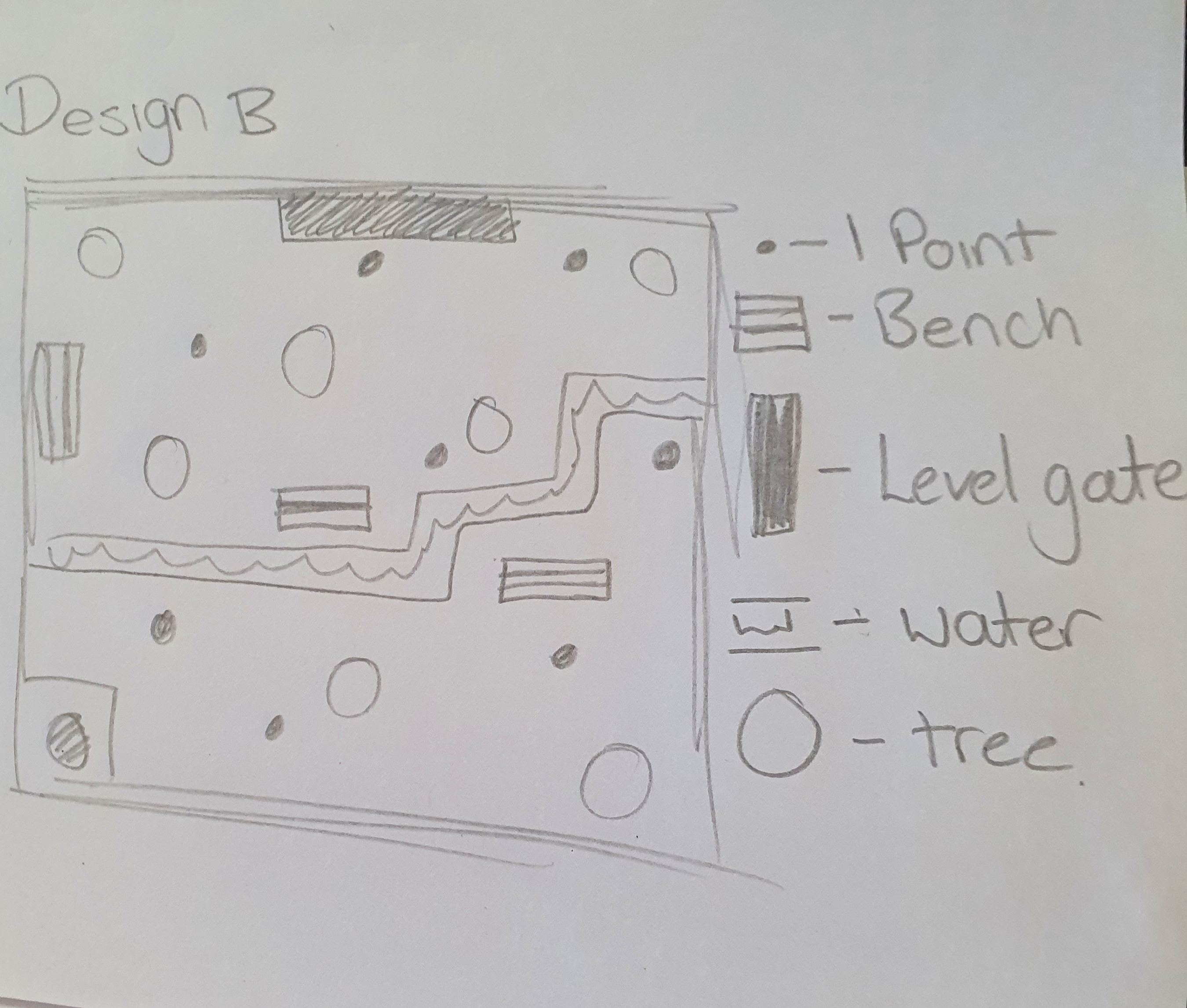
From this position I was able to combine aspects of the two maps to create the final level design I wanted to start developing in 2D Auto CAD. I also added colour to this sketch to further indicate what items and props I wanted located on the level. I also created a side elevation for the level design to show how tall certain items needed to be to ensure they were scaled correctly within the game. All relevant dimensions were shown on these final sketches before I began working in Auto CAD.
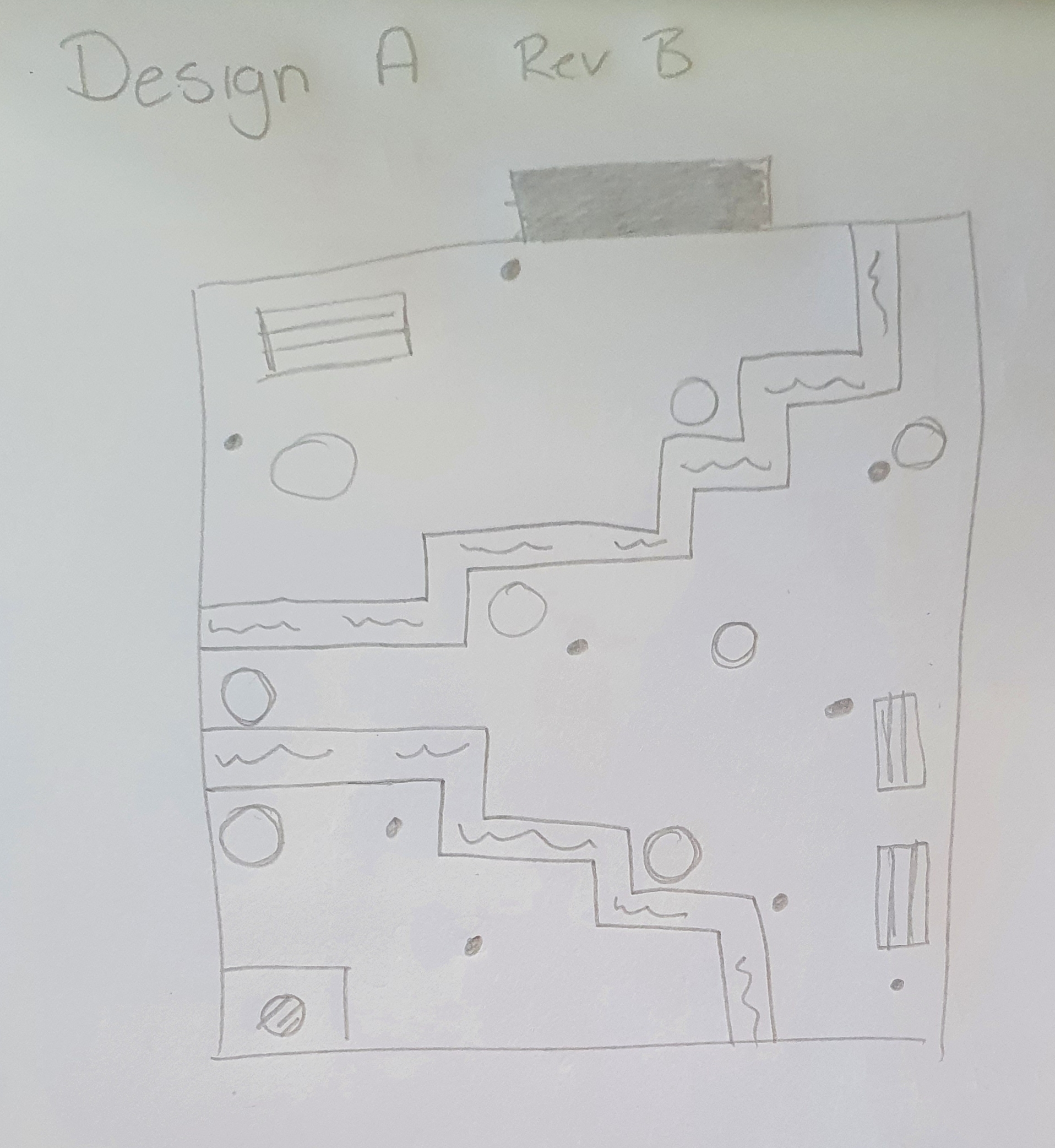
Once in Auto CAD I was able to begin drawing out the plan view of my level sketch. I was able to include all props that were to be implemented into the level. The positions of the items that would increase the users score were also implimented into the level plan along with the staring point for the character. The 2D level plan was then exported to DXF and PDF and sent on to the 3D artist and the developer to allow it to be created and implemented into out unity game.
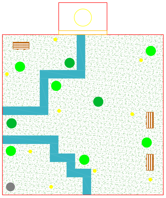
When the level had been designed I was able to give the information of how far and high the character needed to be able to jump. This was to ensure the user could cross both the stream in game and jump on top of the rocks and bench whilst not being able to jump over the perimeter wall. The river is 1.7m wide so the caratcher should be able to jump 1.9m to clear it.
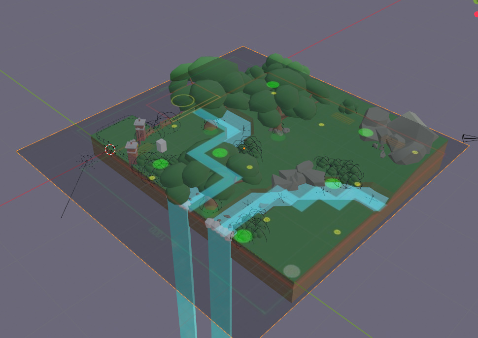
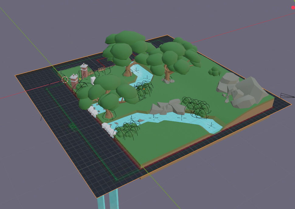
We ensured the level was designed correctly and to the right scale by overlaying my design with the final level creation from unity.
I began researching prop ideas for our game on Pinterest where I was able to create a themed board for any props or designs I felt would work with the theme that our team had agreed upon. this gave me a very good understanding of what I wanted to include into my designs and what I felt would overcrowd the level I was going to set out or interrupt the theme we were trying to achieve.
Once I had researched all the props, I was required to draw for our level design I began to sketch out ideas and my interpretations of how I felt props and items should look within the level. I focused on multiple areas to begin with however once I had roughly sketched these ideas, I found 3 I wanted to focus and develop further to finally be able to draw them in Auto CAD.
Now I had chosen the designs I would like to focus on I began sketching in further detail and adding the colours that were provided by our designer. From here I was able to get the sketches to a good enough level to then proceed to creating the drawings in Auto CAD.
Once in Auto CAD I began by creating the props. I felt like designing in 3D would be the best way for showing my team how I wanted the designs to look once they had been finished. I was able to create all 3 designs as I had sketched them out and I was able to incorporate the right colours to allow the models to appear as they would once they had been designed in unity by the developer and 3D artist.
Each drawing was plotted onto a white paper background and elevations were created to show the different views that would be required for the 3D artist to continue the development stage. These files were sent as PDFs to my group. I was also able to supply DXF files to the 3D artist and developer so they could overlay my drawings to their work to sure the designs are correct.
Mesh Modeling
A mesh Auto CAD model is a 3D model however unlike a 3D solid model it has no mass properties.
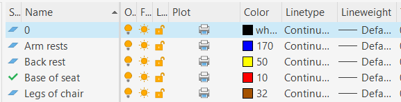
The first 3D mesh model I have created is an arm chair. I began by creating the base for the arm chair as a mesh box. From here I added two boxes with one horizontal face either side of the base so that I could extrude vertically to create the arm rests.
From this position I added a mesh box for the back of the chair. Along with adding 4 extruded legs. Once the chair was complete I altered all layers suit the required names and colours.
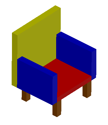
I decided to smooth the arms and back rest of the chair by using the smooth surface tool.

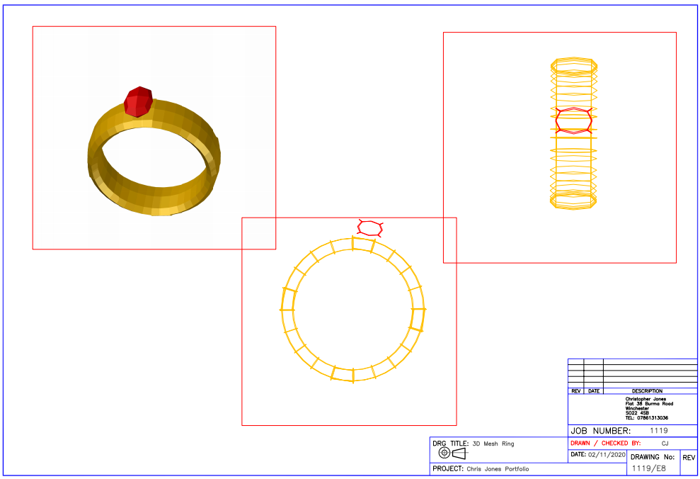
The second mesh model I created was for a ring. I began by drawing a square and joined the lines together. From here I drew a perpendicular line to one of the edges of the square and uses the revolved surface tool to create a 360 degree revolve around the points along the line I chose. This creates a hoop to form the ring.

I then added a mesh square box to the top of the ring to act as a ruby.
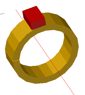
To finish the model, I rounded all surfaces to ensure the model had the appearance of a ring. Layers were then changed to align with the correct names and colour properties required.
Logo Design
To begin with the logo design, I started by creating a mood board in Pinterest showing any eco-friendly items or themes I could find. This allowed me to choose what I felt would tie in with our chosen ideas as a group and our target audience that was stated in the brief.
Once I had found certain elements that I wanted the design to include I began to sketch out some of my own designs for areas of the logo. After sketching a few ideas, I decided to show the group to allow them to choose which they felt worked best for our game. The design that was finally decided on included the world as a background without games character and name in the foreground.
Once as a group we had decided on what we wanted to use I was able to begin drawing the design in Auto CAD to create a 2D plan view of the logo. I decided to develop this further by giving depth to the logo by creating it in 3D. This meant I needed to extrude certain aspects to give the logo a more appealing professional appearance.
Semester 2 Computer Aided Design
During Semester 2 in computer aided design, I was required to further my skills working with 2D and 3D models whilst also learning new skills that will help to complete the numerous tasks that were set for me to complete. These skilld will give me a good understanding of the AutoCAD program to help me in my future employment.
Dimensioned CAD drawings and Data Extraction
To begin the design stages of the device I began by sketching out numerous ideas and areas that I felt had room for development. These areas included how the face of the device should look whilst also looking at how the strap could fit around the users wrist
Using my research I had decided that the face of the device could either be plain or could offer some form of communication to the user to show if the user were too early, late for their train, and show how much battery the device has left. I began by focusing on these two areas as they were very important to how the device would function. I sketched a few ideas of both styles and brought them to my group for discussion.
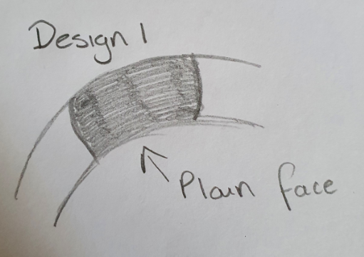
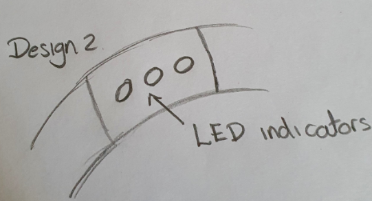
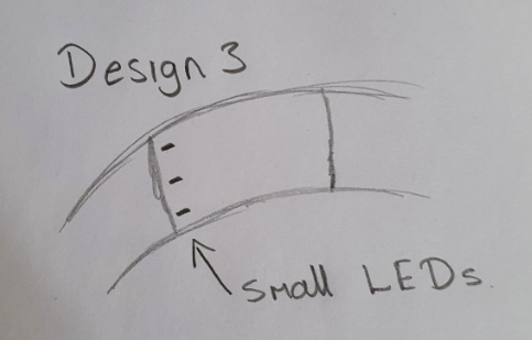
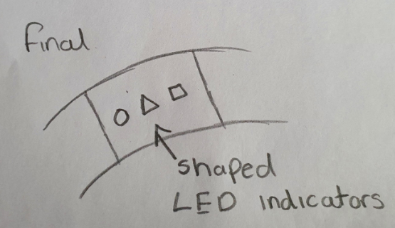
After deciding as a team that it would be more useful for the device to be able to communicate with the user I added three different coloured and shaped LEDs to the front area of the face of the device. Each carrying its own meaning. The Green circle would indicate that the user's train was arriving. The yellow triangle would indicate the Train is 10 minutes away from the users station to embark. The red square would indicate the user only has 10% battery in the device.
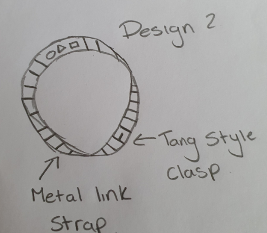
To begin the strap design, I began to look at two possible ideas. The first being a silicone one-piece strap that stretches over a fist and sits around the wrist that is most common on cheaper styles of wristwear due to the low material cost. Option two being a a tang-type buckle as most standard watches use. I began sketching both designs out to give examples of styles in relation to the product we were trying to create.
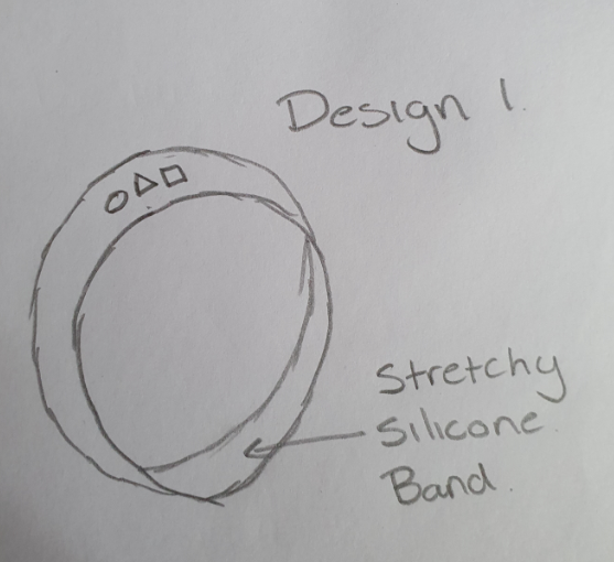
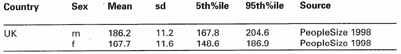
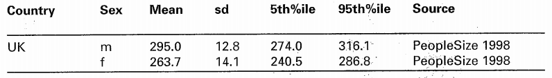
After discussing with the group by showing my design ideas we decided to create a silicone band that would stretch over the users fist. We chose this option as we were keeping cost of creation in mind. This is a factor we would like to keep as low as possible to ensure a reasonable price for customers to ensure the device is in the correct price band for the target audience. This meant I required additional anthropometric data to allow me to see how large the strap would have to stretch by to ensure it would fit.
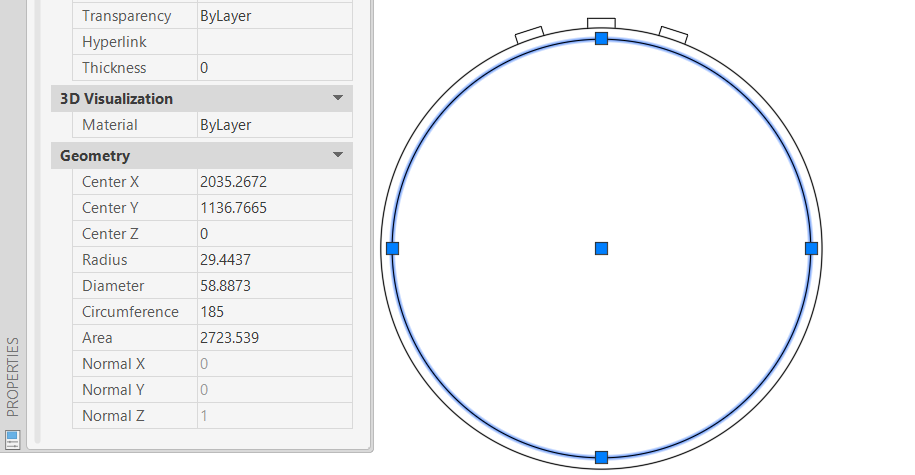
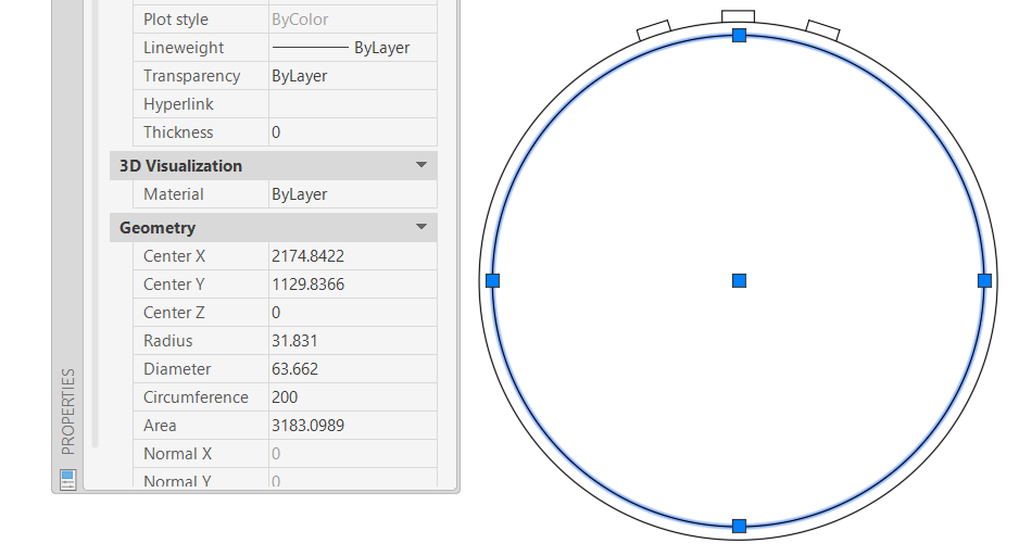
Upon looking at this data I was able to come out with figures of what our device needed to be capable of meeting. I felt it would be best to create the same device in two sizes, one smaller and one larger to help accommodate the varying figures in both age and gender. The smaller bracelet would need to have an internal circumference of 185mm that could stretch to 280mm to allow the user to fit it over the clenched fist. The larger band size would need an internal circumference of 200mm that could stretch to 315mm. Using these two sizes would maximise the comfort for the user and prevent someone with a larger wrist and fist circumference from potentially overstretching and snapping a band size that was made just for the 50th percentile or lower.
From this point I was able to begin modelling in 2D Auto CAD to ensure the sizes I had chosen were correct. It was able to draw the outline of our mobile device to ensure it looked as it was supposed too according to my sketches.
To begin I created some circles to act as the internal and external band diameter to show both normal size on the wrist and size whilst being put on over the fist. These 2D drawings were then put into a drawing border ready to be plotted.
Devoloping your mobile device into a 3D model
When designing in Auto CAD I felt showing the designs in 3D would be the best way to explain and show my team how I planned the designs to look. I began by creating a 2D circle that I could revolve a rectangle around that would have the cross-section dimensions of the silicone band.


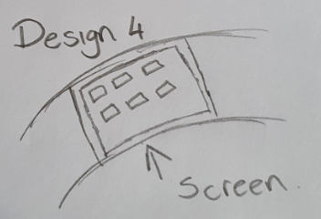
The next step once the band had been created was to create a larger face on one side of the band. This would be on the top of the device and hold the three LEDs. To begin this, I went to mesh modelling and chose face selection. This allowed me to select and extrude individual faces to ensure the top area of the device is large enough for the user to see and that it can hold all the necessary components.

After extruding the necessary areas of the watch face to create the design I required I was able to smooth the surfaces. Smoothing the surfaces allowed the device to take a more realistic shape that you would expect from a silicone watch strap and face. The lights could then be added in the correct positions and given the right shapes. These were small extruded areas on the curved face of the device.


Material mapping and rendering
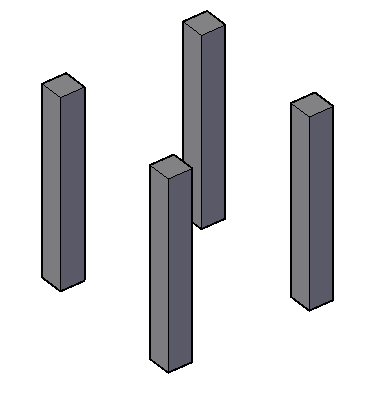
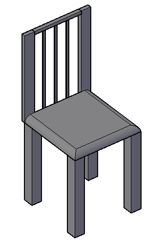
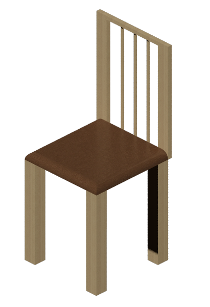
To begin creating a household item in AutoCAD I opened a blank document and set the document to 3D modelling. This allowed me to gain access to the 3D modelling tabs at the top of the page. I started to model by creating a square that was 50x50mm and extruded it by 450mm. this was the copied 3 times to create the legs for the chair.
I then created the seat for the car by using the outside corner of each leg to create a square and extrude upwards. Once I had completed this I radiused each edge of the seat to give a more realistic impression of a chair.
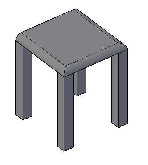
The final part of the chair creation was adding a back rest. This was created by adding some small horizontal squares to the back of the extruded seat. These then in turn were extruded upwards by 600mm creating the final chair.
My next step was to map materials. I opened the materials window by typing material in the command box. I was then able to search through different types of wood to find one suitable for my chair legs and back rest. I also added a brown leather look to the chairs seat. Once this had been added I had successfully mapped the materials and these could be seen in the realistic view.
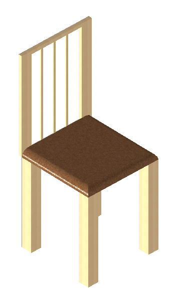
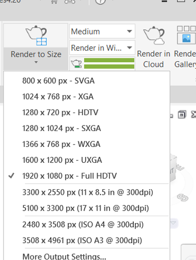
The next step was to render the product. This was done by going to render under the visualise tab. This allowed me to create a rendered image of my final model. The render size was set to the highest quality and 1920x1080 px which is a HD image.
Animation
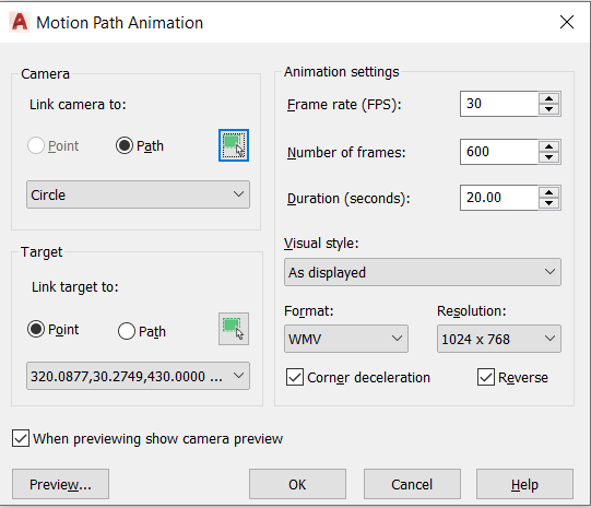
To begin with the animation of my chair from the last exercise I began by creating a large circle around the model. I then used 3d rotate to rotate the circle around the y axis. This allowed me to make the circle that surrounded the model change from vertical to an 80 degree angle allowing for a better view of the model.
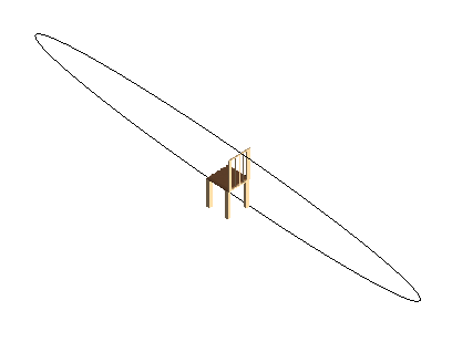
The next step was to create a camera that would follow the path of circle whilst looking at a set point. I completed this by using the anipath command. This brought up a box that required me to select the circle under the link camera to section and select a point of the chair for the camera to focus on in the target box. I then changed the duration to 20 seconds and increased the frames per second to 30. The final change was increasing the quality of the file to 1024x768.
Once the video file had been created, I could view the animation. I then uploded it to Youtube to embed into this website.
External refrences
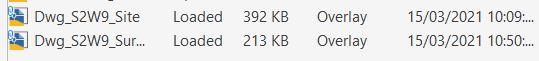
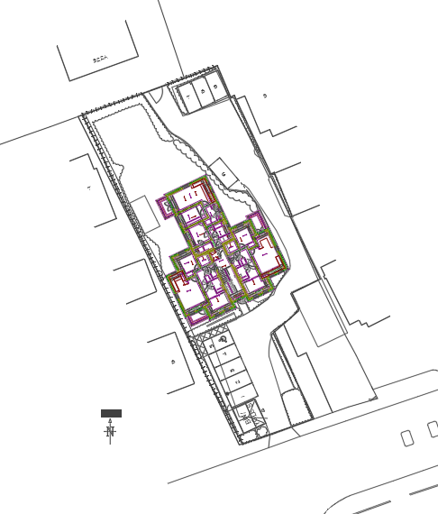
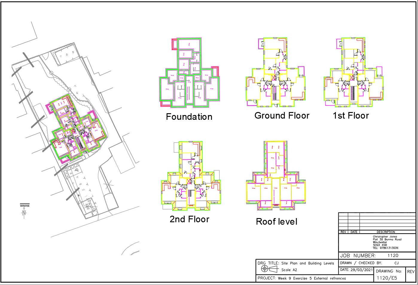
To begin this exercise, I had three separate files. These files all had to be referenced into one file using the external reference command within Auto CAD. To begin with I opened a new Auto CAD document. From here I typed xref into the command bar which opened the xref widow to begin adding the first document. The first .dwg I added was the site plan. This was inserted in the correct position as to where it should be in the document. The second file I imported was the site survey. This ensures that the site plan fits correctly on to the survey that was completed. I used the same settings to import these references as shown below.
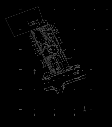
Once these files had been added and overlayed each other in the correct way I could begin to change the colours of the layers and turn off certain layers that were not required. This allowed me to choose only the information that I required to be shown. Once I had simplified the drawings that were now referenced in the document, I could begin to work on the third document that needed to be referenced.
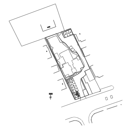
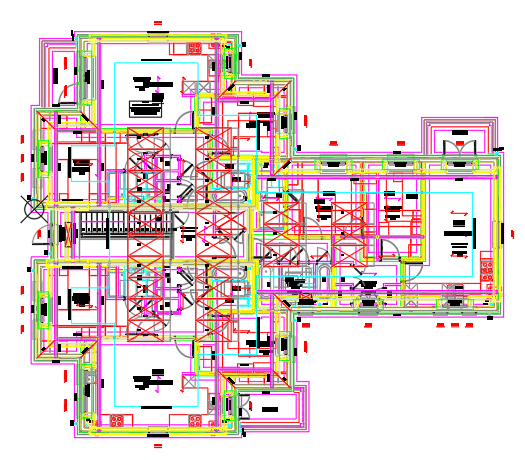
Before I could add the architects drawings into the final reference document. I first had to split the multiple drawings that were in the one file into their own separate files. This was done by first moving each of the drawings over the top of one another to ensure they were all in the same position. Next, I began to copy each level of the building into its own file and save them as their floor level.
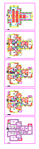
I then referenced each of the 5 levels into the reference document. However, when I referenced them in, I found they werent in the correct position or the correct scale. To solve this, I changed the settings on the xref window to scale the position of the 5 drawings to 0.1 on a uniformed scale this ensured the 5 drawings were now in the correct position however they were in the wrong orientation as the site plan and survey were correct to north on a compass and the architects drawings were drawn at 90 degrees in a standard document.
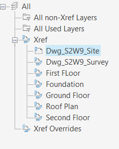
Once I had used the angle measure tool to find the difference between the site plans and architects drawings, I was able to apply a rotation of 116 degrees in the properties window to the architects drawings. This ensured the 5 drawings were aligned correctly and in the right position when compared to the site plan and survey.
I then altered the layer properties to only show the relevant areas of the architects drawings. From this stage I was able to begin to create a drawing on an A2 sheet to show the whole site survey whilst also showing each individual levels. The DWG document can be downloaded below along with the files that have been referenced.

Dynamic blocks
A dynamic block is a block that can be inserted into Auto CAD as any other block however it has pre-set values that can be selected by the user to change the rotation, length, or scale of the object to fit the required needs of the user.
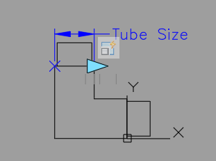
The first dynamic block I created was for a 90-degree stainless steel handrail joint. The main parameters I had to set were orientation and scale for this piece.
To begin this, I created a standard 90-degree stainless steel handrail corner that would fit an inline 42 diameter handrail. This was then joined together.
Next, I typed block into the command bar and set up the block creation. I selected a base point on the drawing and selected the whole object as I required the whole item to be brought into the block creation. I also ensured scale uniformly was checked and the block unit was in millimetres.
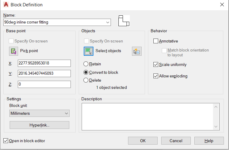
From this point I was able to begin with the dynamic block creation. I started by adding a parameter for the area I wanted to ensure was a certain size. For this block it was the width of both ends of the connector. I wanted this to scale uniformly with the rest of the block depending on the size of the handrail it had to connect to e.g. 48mm or 66mm. Once my distance 1 parameter had been set I was able to apply the scale action to it.
Once the scale action had been selected, I was able to click the parameter I wanted to link it too. I then selected a grip on the parameter that I wanted to use as the point that would be used to select the required size for the item. Finally, I selected the whole object as I wanted the whole object to be affected by the scale.
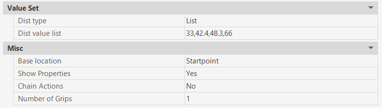
After this had been completed, I could input my distances that I wanted the object to be scaled too. I firstly clicked on the parameter and typed properties. This allowed me to se the properties that were linked with this parameter. From here I changed the settings from two grips to one grip as I only required a grip on one side of the parameter. I also changed the distance type from none to list. This then allowed me to enter my required values for which I chose; 33, 42.4, 48.3 and 66mm. These are the most common handrail sizes in industry. To check this had worked correctly I used the test block feature and the block was able to scale correctly to my set distances.
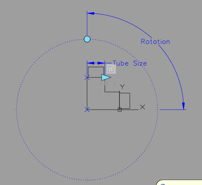
I was then able to add a rotation factor into the block. This would allow the user to orientate the 90-degree fitting to any corner they wanted. I first set the angle parameter to the outside corner of the object. I then selected 90 degrees as a standard starting point.
I then applied the rotate action and applied it to the rotate parameter then selected the whole block. I was then able to again select the properties of the rotate parameter and input the values I wanted to rotate the block by. These were 0, 90, 180, 270 degrees.
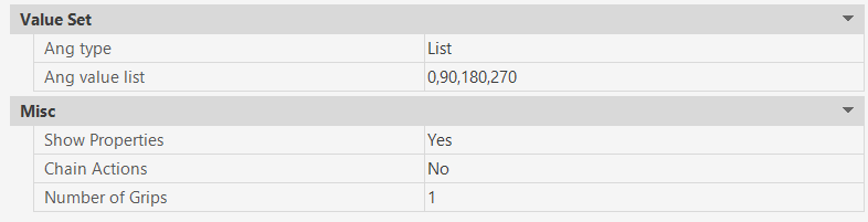
The final block can be downloaded below.
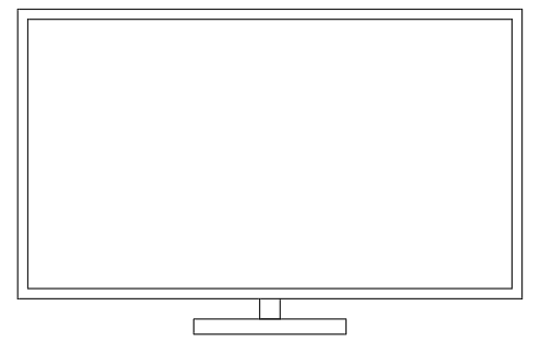
The next block I created was a TV screen size block. This would help the user insert a screen into Auto CAD and allow them to change the screen size based on the television size the required. This would be very useful for an interior designer or someone who was planning a living space within a home or business.
I began by drawing out a 2D television shape on Auto CAD. From here I joined all the lines together ready to create the dynamic block.
Then typed block into the command bar to create the block I would need. I called the block TV and set the base point as the centre of the stand. I also selected all the objects as I would require all of them in the block creation. Finally, I ensured the block units were in millimetres and the scale was uniformed.
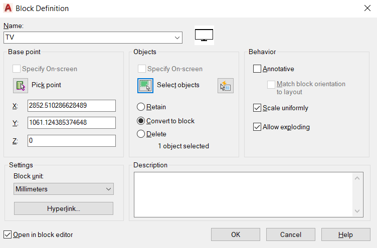
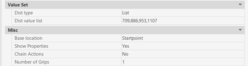
Once I was in the block creator, I researched how big screen sizes were in millimetres. This allowed me to see how many variables I would need to add to my parameter. I added a linear parameter to the inside of the screens edge and selected a scale action.
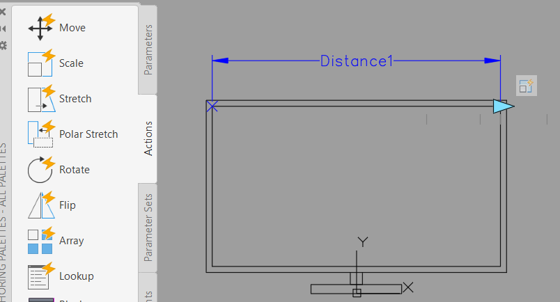
After the action had been placed on the parameter and the whole object had been selected, I went to the properties of the linear parameter and changed the distance type from none to list. Again, I placed in my figures of screen widths in millimetres that I had found from my research. As I selected the whole screen on the scale action when the screen width is made wider. The whole tv will get bigger. This is good for this action as the aspect ration of the screen will stay correct for every screen width size. This is due to the original screen I drew to create the block was scaled from a 42-inch TV screen.
I finally tested this block using the block test tool before saving it.
The screen block can be downloaded here.
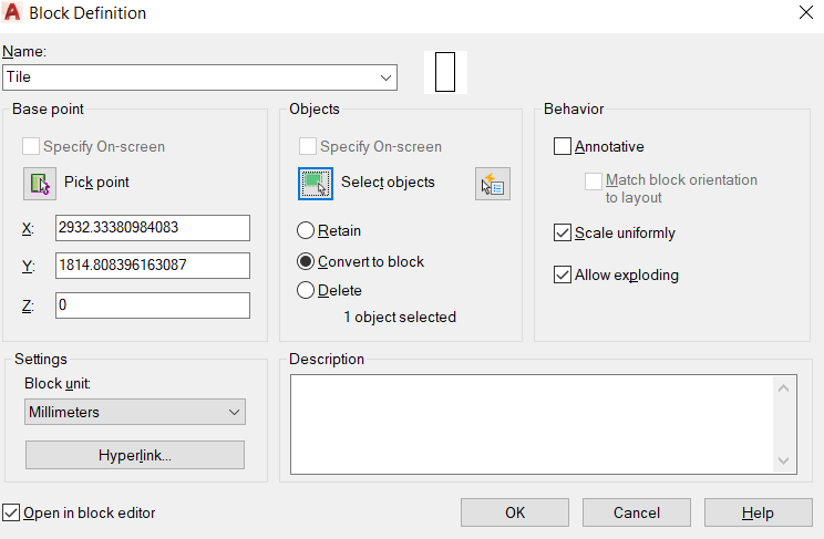
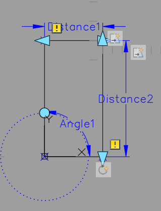
My third dynamic block I created was for a floor tile. I started by drawing a floor tile in 2D Auto CAD. I then typed block to create dynamic block that would involve changing orientation, length, and width.
Once in the block creation screen, I added two linear parameters that one along the width and one along the length of the tile. I then selected the stretch action and selected each parameter and highlights the two different sections of the tile I wanted to move on each of the commands. For the width it was the left-hand side of the tile and for the length it was the top section. This told Auto CAD which areas to stretch when told to do so.
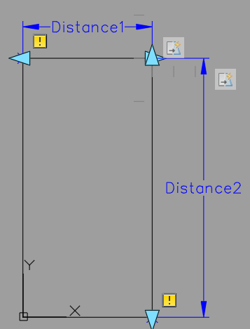
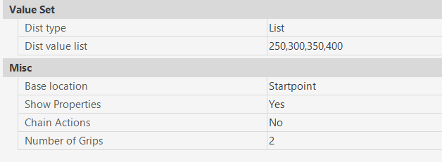
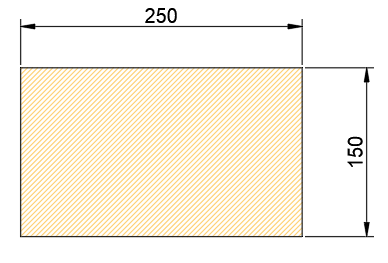
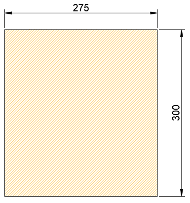
I then entered the values for the length of the tile in the properties menu. These were 250, 300, 350 and 400mm.
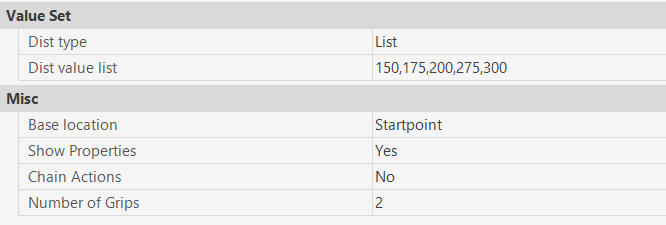
After this I entered the values for the width of the tile in the properties menu. These were 150, 175, 200, 275 and 300mm.
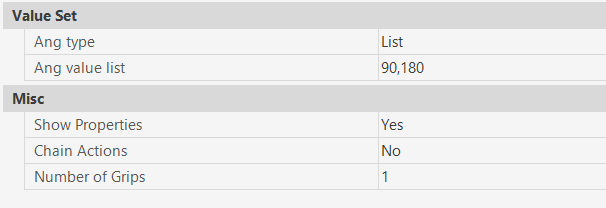
I then wanted the tile to rotate 90 degrees and offer the user the same size options in a different orientation. This meant I had to add a rotate parameter to the bottom left corner of the tile and apply the rotate action. When selecting the tile outline for this action I also select the with and length parameters as I also wanted these to rotate with the tile. In the properties window I was also able to add the angles of 90 and 180 degrees to the list of options that the tile could rotate.
After completing the dynamic block, I went back to the paper-space and hatched the internal area of the tile. This gave the tile a pattern and colour. This hatched area will also automatically change with the tile size and orientation selected by the user.
Command Shortcuts
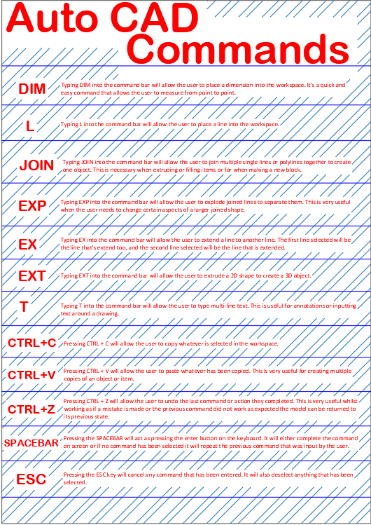
The command shortcuts poster has been created in Auto CAD to show some of the most common and important commands and buttons that a user can input. It highlights multiple areas of 2D and 3D modelling. The commands listed make the user experience easier once learned and they speed up the production of drawings and models. However, in some cases there are multiple ways of entering each command; there are the shortcuts as listed on the poster and they are also available from the command ribbons at the top of most Auto CAD documents depending on the users personal set-up.